OPM_LPS_31E_8K0_20K_1GB_V010.doc 11/40 Operating Manual LP 31 / 8-10-15-20 kVA
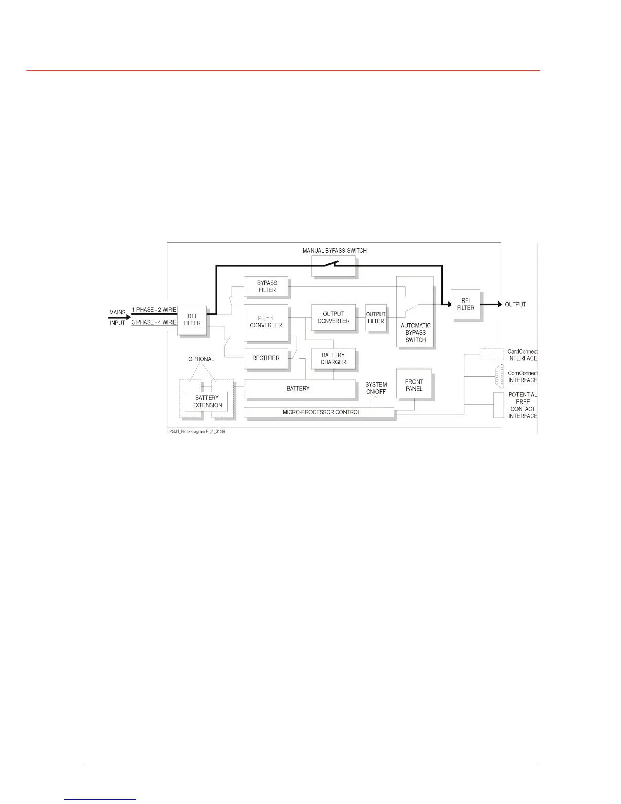
2.6 MANUAL BYPASS SWITCH
The system can be bypassed manually using the manual bypass switch located at the rear
panel.
It is a two-position switch: the normal position is “1”: as in figures 1-2. Position “2” is the service
position: the load is directly connected to the mains input.
This way, testing and maintenance of the UPS is possible without interruption of the power
supplied to the load.
Figure 4 - Bypass operation: manual bypass