ALIGNMENT AND TROUBLESHOOTING PROCEDURES
12 LBI-38438A
5.1.2 TX VCO & RX VCO Alignment
CMC-232A 29.7 - 42 MHz
STEP
METERING
POINT
TUNING
CONTROL
METER
READING PROCEDURE
1TP201
Control
Voltage
Monitor
L206 4.0 VDC
7.0 VDC
In case highest transmit frequency is
< 34.0 MHz
. Select lowest frequency
transmit channel. With 50 ohm load on
the antenna connector J1, key the radio.
Monitor TP201 with digital voltmeter
and tune L206 for 4.0 VDC ±0.1 V.
Unkey the radio.
In case the highest transmit
frequency is > 34.0 MHz.
Select
highest frequency transmit channel.
With 50 ohm load on the antenna
connector J1, key the radio. Monitor
TP201 with a digital voltmeter and tune
L206 for 7.0 VDC ±0.1 V. Unkey the
radio.
2 TP201 CV201 7.0 VDC Select the highest frequency receive
channel. Monitor TP201 with digital
voltmeter and tune CV201 for 7.0 VDC
±0.1 V.
3 TP201 3.5-7.5
VDC
Select lowest frequency channel.
Voltage should be between 3.5 – 7.5
VDC transmit and receive for lowest
and highest frequency channels.
4 J201 +1 to +8
dBm
RX/EX injection level should be
between +1 and +8 dBm.
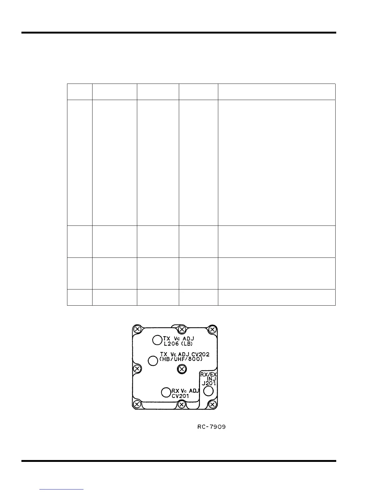
NOTE:
Refer to Figure 5 for location of tuning and adjustment controls.
Figure 5 –
Synthesizer
Tuning and Adjustment Controls
CMC-232B 42 – 50 MHz