3
CHANGE COOKTOP BURNER
ORIFICES (CONT.)
14
Installation Instructions
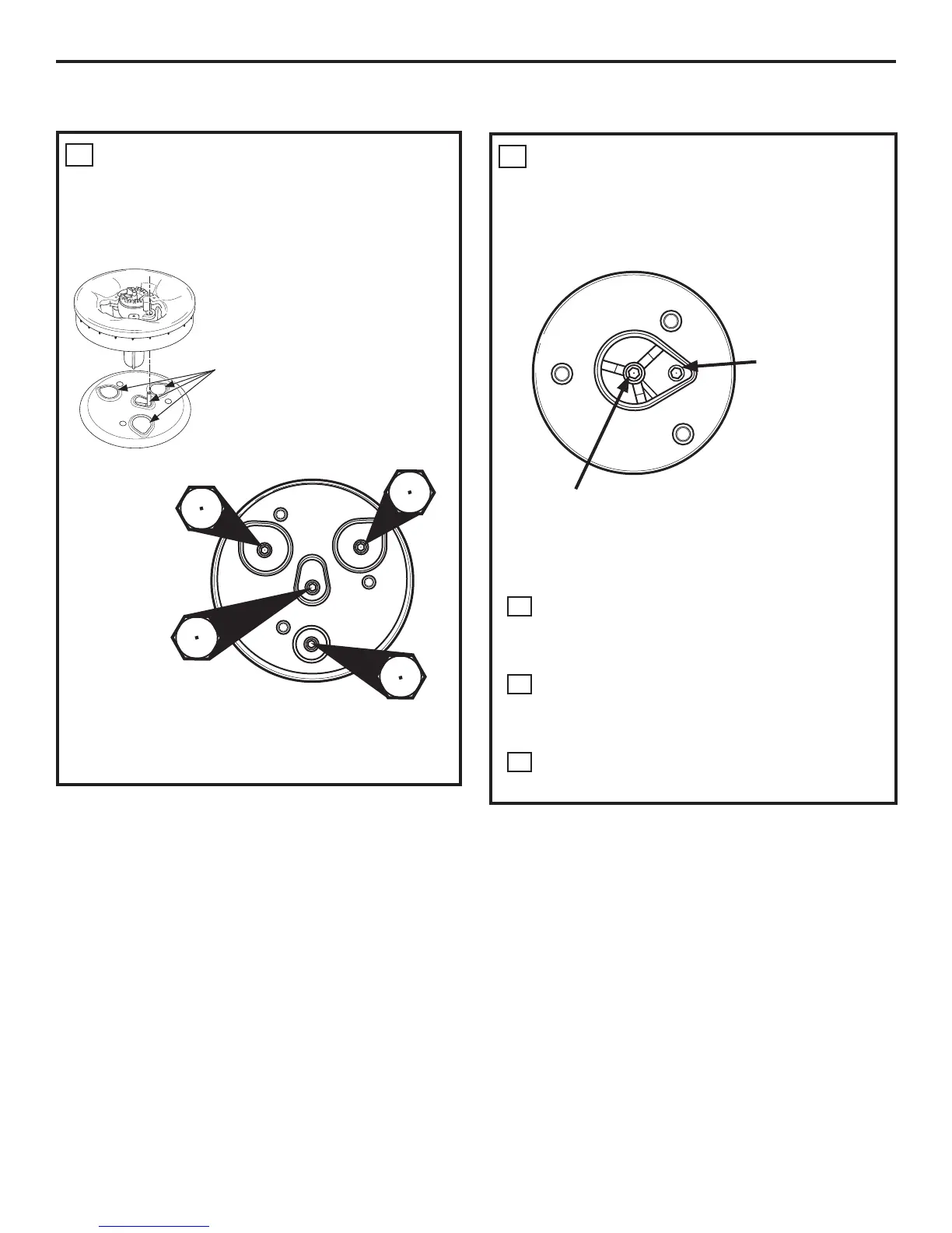
3
CHANGE COOKTOP BURNER
ORIFICES (CONT.)
CENTER BURNER
20,000 BTU/hr Tri-Ring Burner (PGP986 and CGP650
Models)
Orifice spuds located
through these
openings.
V
Main Orifice
Main Orifice
Main Orifice
Simmer Orifice
V
V
V
(Shorter)
51L
58L
58L
58L
LEFT FRONT BURNER
(PGP986 and CGP650 Models)
Main Orifice
Griddle Screw
The griddle screw
is marked with N
for natural gas
and L for liquefied
petroleum.
NOTE: The main orifice is located in the center of
the burner, while the griddle screw is located to the
right of the center of the burner.
D
Install the LP Propane orifices and griddle
screw (on PGP986 and CGP650 models only)
in their precise locations as noted in the
earlier illustrations.
E
Return the natural gas orifices and griddle
screw to the bracket and attach the bracket
and the instruction sheet to the pressure
regulator using the screw removed previously.
F
Replace the burner heads, caps and grates.
 Loading...