

M
Michael CruzJul 28, 2025
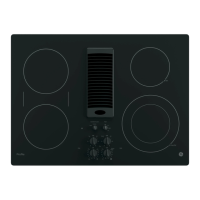
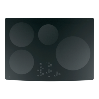
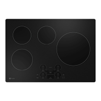
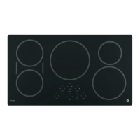
What to do if touch keys are not working on GE Profile PP945 Cooktop?
- BBethany CarrollJul 29, 2025
If the touch keys on your GE Cooktop aren't responding correctly, it might be due to water or other contaminants causing unwanted ground coupling. Clean the keypad glass, making sure it's dry, and then wait 30-60 seconds for the keypad sensitivity to stabilize. If the issue persists, there may be a gap or moisture between the touch board and the glass, in which case the glass assembly should be replaced.