CAUTION:
Over tightening the locking screw may damage
or distort the case of the accessory.
Catalog Number/
Control Voltage
Primary
Connections
Secondary
Connections
9T58K0042 / 480 V
H1, H4 ➀
X1, X2
9T58K0062 / 600 V
H1, H4
X1, X3
Tighten the locking screw on the front of the accessory
until it is snug (torque of 9 in-lb.)
If the breaker is equipped with a MicroVersaTrip Plus or
MicroVersaTrip PM Trip Unit, the UV R accessory can be
configured to activate installed Bell Alarm–Alarm Only or
Bell Alarm with Lockout accessories when a UVR trip
occurs, with the procedure described in the Accessory
Configuration section.
Mount the supplied step-down transformer near the
circuit breaker.
Connect the control wiring for the UVR to the primary
side of the transformer, marked as the H-numbered
terminals. Table 2 lists the correct transformer primary
taps.
WARNING:
480 Vac and 600 Vac Undervoltage Release
accessories must be used with the supplied step-down
transformer.
AVERTISSEMENT:
Les modules de déclenchement
à manque de tension 480 Vac et 600 Vac doivent être
utilisés avec le transformateur abaisseur de tension qui
est
Test the UVR to ensure proper operation, according to the
procedures below.
Reconnect power to the circuit breaker and any other
accessories.
Close and lock or seal the door over the accessory
compartment and Trip Unit to prevent unauthorized
changes to Trip Unit settings and to keep contaminants
out empty accessory slots.
Accessory Configuration
This section of only applies if Bell Alarm–Alarm Only or Bell
Alarm with Lockout accessories are installed in the breaker,
along with a MicroVersaTrip Plus or MicroVersaTrip PM Trip
Unit. If the breaker is equipped with a Power+ Trip Unit, the
factory default settings, listed in Table 3, cannot be changed.
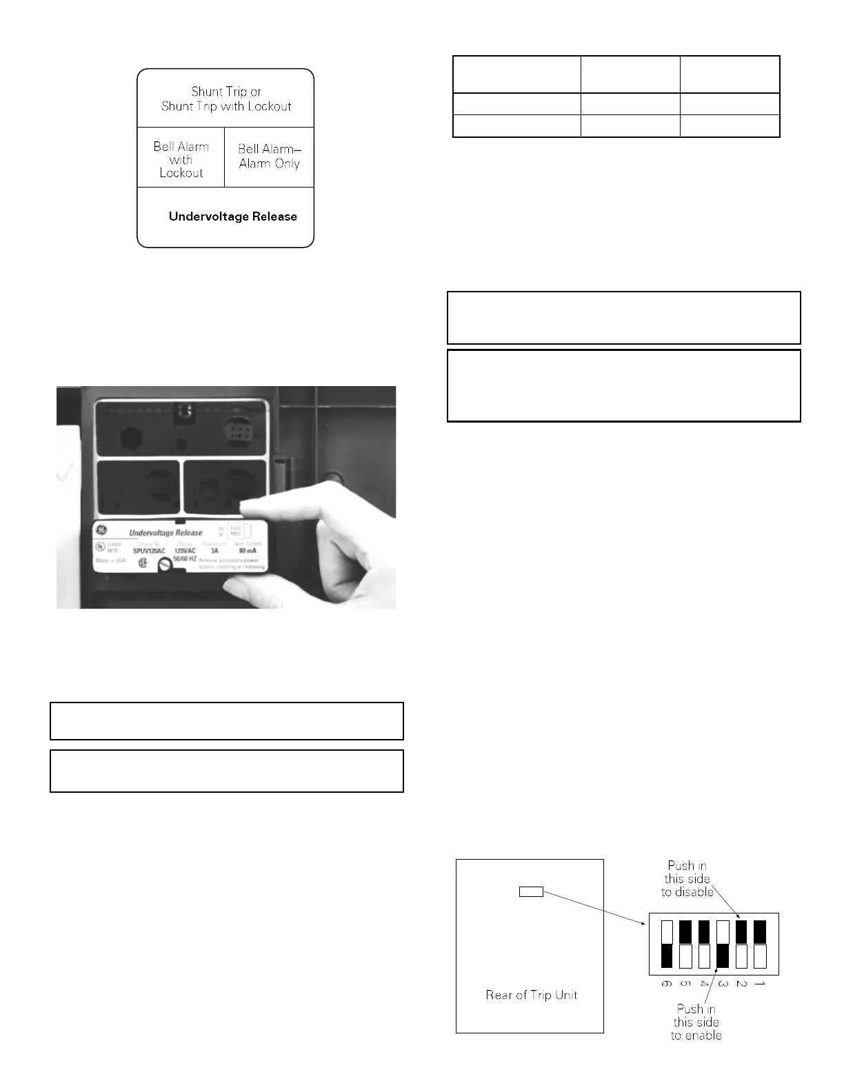
The UVR accessory can be configured to activate the
Bell Alarm–Alarm Only or Bell Alarm with Lockout accessories
if a UVR trip occurs. The configuration can be changed
by removing the Trip Unit from the breaker, setting the
DIP switches on the rear of the Trip Unit, and reinstalling the
Trip Unit. Figure 4 illustrates the Trip Unit read DIP switches
and their functions. Table 3 lists the switch functions and
the factory settings for each.
ATTENTION:
Le serrage excessif de la vis de verrouillage
peut déformer le boîtier d’accessoire.
—
Figure 4. Accessory switch on the rear of the MicroVersaTrip Plus™ or MicroVersaTrip PM™ Trip Unit,
showing the factory settings (solid part indicates that the switch is pushed in on that side).
Insert the UVR accessory into the proper slot, as
illustrated in Figure 3. The UVR accessory is keyed for
the correct slot in the accessory compartment. If the
accessory cannot be fully seated in the compartment,
check that the compartment position is correct.
—
Figure 3. Inserting the Undervoltage Release into the accessory compartment.
➀
A jumper must be placed from H2 to H3.
—
Table 2. Primary and secondary connections for step - down transformers
Connect the secondary side of the transformer, marked as
the X - numbered terminals, to terminals 29 and 30 of the
terminal block on the right side of the breaker. Table 2 lists
the correct transformer secondary taps.
—
Figure 2. Accessory compartment on front of circuit breaker, with Undervoltage Release slot indicated.
3.
4.
5.
6.
7.
8.
9.
10.
11.
2
 Loading...


