EasyManua.ls Logo

GE Profile Arctica Series User Manual

GE Profile Arctica Series
2 pages
To Next Page IconTo Next Page
Page #1 background imageLoading...
Page #1 background image
N.D. 366-50
GE Appliances
General Electric Company
Appliance Park, Louisville, KY 40225
Service Bulletin
REFRIGERATORS REF 34-02
ARCTICA SIDE-BY-SIDE
CUSTOMCOOL MODELS
TROUBLESHOOTING FLOW CHART
SEPTEMBER 2002
The troubleshooting flow chart included in
this bulletin was developed in order to
successfully troubleshoot and diagnose
malfunctions in the electronic control system
of the GE Profile Arctica™ Side-by-Side
refrigerators with CustomCool™ techology.
CUSTOM COOL
GE SmartWater
Plus
DELIFRESH
DELIFRES
H
FRESH PRODUCE
WATER
RESET WATER FILTERLIGHTDOOR ALARMLOCK CONTROL
CRUSHED
CUBED QUICK ICE
This troubleshooting flow chart will help
technicians:
• Quickly determine the exact problem
• Use standard tools
• Determine what parts, if any, to be replaced
• Avoid repeat service calls
• Avoid unnecessary replacement of parts
GE Profile Arctica Side-By-Side Refrigerator
with CustomCool Technology
Question and Answer IconNeed help?

Do you have a question about the GE Profile Arctica Series and is the answer not in the manual?

GE Profile Arctica Series Specifications

General IconGeneral
Energy Star CertifiedYes
Ice MakerYes
Water DispenserYes
Defrost TypeFrost-Free
ShelvesGlass Shelves
Width35.75 in

Summary

Service Bulletin Introduction and Purpose

Bulletin Identification

Service Bulletin REF 34-02 for GE Appliances.

Scope of Troubleshooting Flow Chart

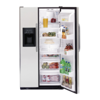
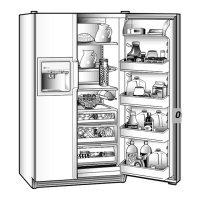
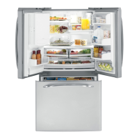
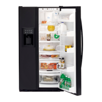
Details the troubleshooting of electronic control systems in GE Profile Arctica™ Side-by-Side refrigerators with CustomCool™ technology.

Benefits for Technicians

Outlines how the flow chart helps technicians quickly diagnose problems, use standard tools, and avoid unnecessary part replacements.

Arctica Refrigerator Main Board Troubleshooting Flow Chart

Initiating the Troubleshooting Process

Starts with checking temperature settings and basic functions like dispener operation and compartment lights.

Power and Connection Checks

Involves verifying AC/DC power connections at the main board, checking fuses, and inspecting wiring.

Component-Specific Troubleshooting

Guides through diagnosing issues with door switches, evaporator fans, and thermistors.

Board and System Replacement Steps

Details steps for replacing temperature boards, membranes, or the main board if problems persist.

Related product manuals