29-6094 17
4
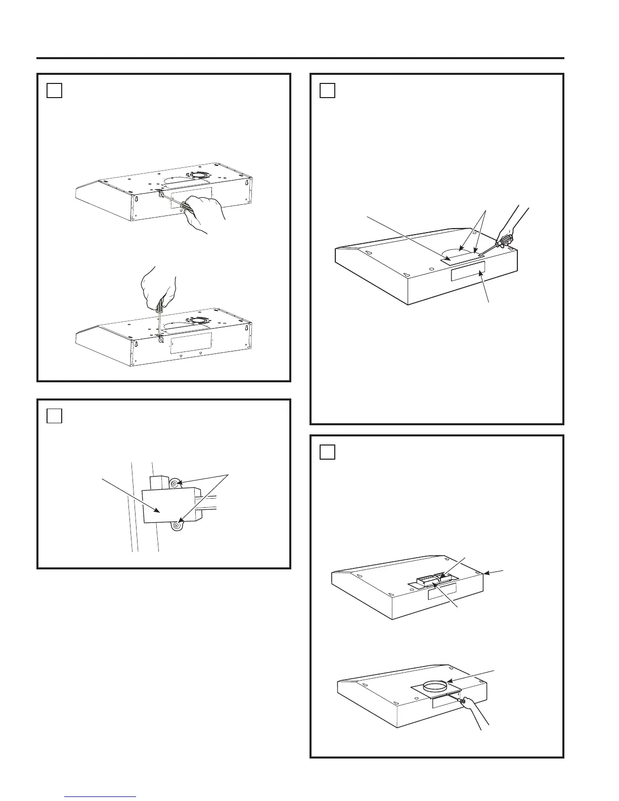
REMOVE ELECTRICAL
KNOCKOUTS
Use a flat blade screwdriver, remove the
appropriate electrical knockout from the back or
the top of the hood.
5
REMOVE JUNCTION BOX
Remove junction box from inside the hood. Set
the junction box and mounting screws aside.
6
REMOVE DUCT KNOCKOUT(S)
FOR VENTED INSTALLATION
Determine which ducting option to use.
Using a flat blade screwdriver, remove the
appropriate duct knockout(s) from the top or
back of the hood.
NOTE: If the hood is to be installed in a
recirculation, non-vented ductless manner, do not
remove any venting knockouts.
NOTE: For an ENERGY STAR
®
model, unit must
be vented mode to be considered ENERGY STAR
®
certified.
7
ATTACH DAMPER/DUCT
CONNECTOR
Attach damper/duct connector over knockout
opening with two or four (D) screws. Make sure
damper pivot is nearest to top/back edge of
hood. Remove any packaging tape to allow
damper to move freely.
INSTALLATION PREPARATION
Installation Preparation
3
1
»4” x 10” Rectangular
vertical discharge. Remove top
rectangular duct knockout only.
7” Round vertical discharge.
Remove semi-circular duct
knockout and top rectangular
duct knockout.
3
1
»4” x 10” Rectangular horizontal
discharge. Remove rear rectangular
duct knockout only.
Rectangular Ducting
Round Ducting
Damper (vertical discharge
position shown)
7RSEDFN
edge
Tape
7” round
exhaust
adaptor
Junction Box
Screws
1" = 2.5 cm; 1' = 0.3 m