Do you have a question about the GE PWR04FANBB and is the answer not in the manual?
Introduction to the GE Profile Wine Chiller technical service guide.
Critical safety notices, warnings, and grounding device reconnection instructions.
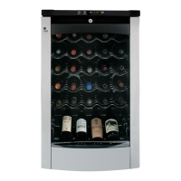
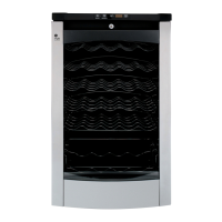
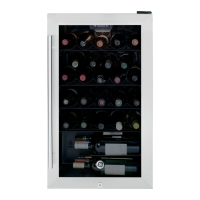
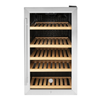
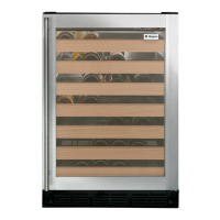
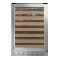
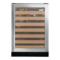
Lists features, dimensions, clearance, and weight of the wine chiller.
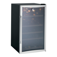
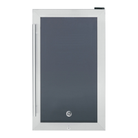
Describes the door assembly, gasket, and stop mechanism.
Details the interior light circuit, bulb type, and testing.
Explains the display board, its components, and access procedure.
Instructions for accessing the main control board and its wiring connectors.
Step-by-step guide to enter, use, and exit the service test mode.
How to test the thermistor and its resistance values at various temperatures.
Instructions for replacing the evaporator and required connectors.
Information on using ferrite filters to prevent interference.
Provides technical data on refrigeration system pressure, charge, and performance.
Details installation clearances and the system's electrical/refrigerant schematic.
Illustrates the door assembly components with reference numbers.
Shows the main cabinet components and shelving with reference numbers.
Illustrates components located at the base of the unit with reference numbers.
A comprehensive table listing all replacement parts with view numbers and descriptions.
| Brand | GE |
|---|---|
| Model | PWR04FANBB |
| Type | Wine Cooler |
| Capacity | 4 Bottles |
| Cooling System | Thermoelectric |
| Color | Black |
| Door Material | Glass |
| Energy Star Certified | No |