Do you have a question about the GE RPV311 and is the answer not in the manual?
Provides a functional and technical description of the RPV311 and instructions for use.
Details the RPV311 and RA33x modules as a distributed solution for Multifunction Digital Recording.
Highlights the main features of the RPV311 plus RA33x acquisition modules solution.
Information for personnel on safe handling, operation, and emergency procedures.
Details electrical hazards and precautions for personnel involved in installation and servicing.
Lists compliance with European directives on EMC and LVD, including product safety and environmental standards.
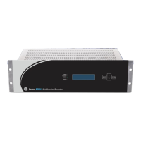
Describes the RPV311 multifunction processing unit and its acquisition system.
Covers the mechanical aspects and main features of the RPV311 unit.
Details the key features and components of the RA331 acquisition module.
Details the key features and components of the RA332 acquisition module.
Details the key features and components of the RA333 acquisition module.
Instructions on how to access and log in to the equipment's web interface for configuration.
Configuration options for time synchronization using IRIG-B or NTP.
Details on communication interfaces via Ethernet and serial ports.
Configuration of user access levels, passwords, and security settings.
Configuration of monitoring thresholds for various electrical quantities.
Configuration settings for triggered and continuous fault recording.
Configuration for steady-state recorders including average series, harmonics, and flicker.
Details the RPV311's local interface for human-machine interaction.
Instructions for accessing and navigating the equipment's monitoring web interface.
Allows manual triggering of equipment recordings without exceeding thresholds.
Describes how to access different types of records stored on the RPV311.
Guides on graphically monitoring circuit and DC channel quantities via the web interface.
Details on how fault records are created, their recorded values, and timing.
Information on recording traveling wave data for fault location analysis.
Describes the creation of steady-state records like Average Series, Harmonics, and Flicker.
Specifies record file formats, naming conventions, and mass storage capacity.
Provides an overview of the Traveling Wave Fault Location architecture and operation.
Details the automatic TW fault location capability using RPV Manager software.
Explains the calculation of the K factor for overhead transmission line sections.
Describes synchrophasor measurement and broadcast according to IEEE C37.118.
Details the accuracy limits and Total Vector Error for PMU measurements.
Provides an overview of MODBUS registers for SCADA integration.
Explains how to manually associate analog data to MODBUS register numbers.
Details DNP3 registers and SCADA integration via Ethernet.
Information about associating digital channels with IEC61850 GOOSE messages.
Overview of RPV Tools suite for PC applications: Scanner, Config Tool, Fault Locator, GOOSE Configurator.
Step-by-step guide for installing the RPV Tools applications on a PC.
Description of the Scanner tool for sequential record scanning and transfer.
Details on creating, sending, and managing equipment configurations offline and online.
Explains the TW Fault Locator tool for analyzing traveling wave signals to locate faults.
Overview of the RPV Manager's main interface, including system monitor and record display.
Configuration for automatic download and refreshing of equipment records.
Details user settings for file management, device configuration, and polling.
Access to various tools within RPV Manager for alarms, fault location, and record history.
Features automatic TW fault location capability using COMTRADE registers.
Details the RPV311's communication interfaces: Ethernet, serial, and optional optical Ethernet.
Describes the electrical and optical Ethernet ports for configuration, monitoring, and GOOSE.
Information on the serial communication port for modem connection and record transfer.
Lists communication ports and their associated protocols and uses.
Instructions for local communication via an electrical Ethernet port.
Covers requirements for receiving, unpacking, and storing the product.
Assures integrity, protection, and user safety during normal equipment operation.
Details mechanical installation requirements for the RPV311 and RA33x modules.
Provides guidance on connecting AC or DC power sources within specified limits.
Shows wiring diagrams and specifications for RPV311 power connections.
Instructions for connecting the protective earth terminal for EMC compatibility.
Details how to connect acquisition modules to the RPV311 processing unit via fiber-optic links.
Configures analog inputs for voltage measurement on RA331, RA332, and RA333 modules.
Describes high-speed analog inputs for Traveling Wave voltage measurement on RA333.
Configures analog inputs for current measurement on RA331, RA332, and RA333 modules.
Details configuration for DC transducer inputs measuring voltage signals.
Details configuration for DC transducer inputs measuring current signals.
Information on insulated digital inputs for RA331, RA332, and RA333 modules.
Explains time synchronization using IRIG-B signals for data acquisition.
Guidelines for regular checks to ensure correct operation and integrity of the equipment.
Troubleshooting common issues with the RPV311 processing module.
Troubleshooting common issues with the RA331, RA332, and RA333 acquisition modules.
Procedure for returning equipment to Alstom for repair services.
Technical specifications for the RPV311 unit, including Ethernet and optical ports.
Details of the electrical Ethernet ports for configuration, monitoring, and GOOSE.
Specifies the power supply requirements and ranges for the RPV311.
Lists EMC tests performed according to IEC 60255-26 standards.
Details safety tests performed according to IEC 61010-1 and IEC 60255-5.
Technical specifications for analog acquisition at 50/60 Hz.
Specifications for voltage inputs, including nominal voltage and accuracy.
Specifications for current inputs, including nominal current and accuracy.
Specifications for DC transducer inputs for voltage and current measurements.
Illustrates various voltage signal connection diagrams for 3-phase circuits.
Shows connection diagrams for one 3-phase circuit (phases A, B, and C) for TW inputs.
Illustrates different current signal connection diagrams for 3-phase circuits.
Contains information on threshold violations, triggers, data recording, and alarms.
| Microphone | Built-in microphone |
|---|---|
| PC Connectivity | USB |
| Battery Type | AAA |
| Voice Activation | Yes |
| Display | LCD |