RPV311
Distributed Multifunction Fault Recorder
Chapter 7: TW Fault Locator
This chapter provides information regarding the architecture and the proper use of
the Reason Traveling Wave Fault Location.
1 TWFL Overview
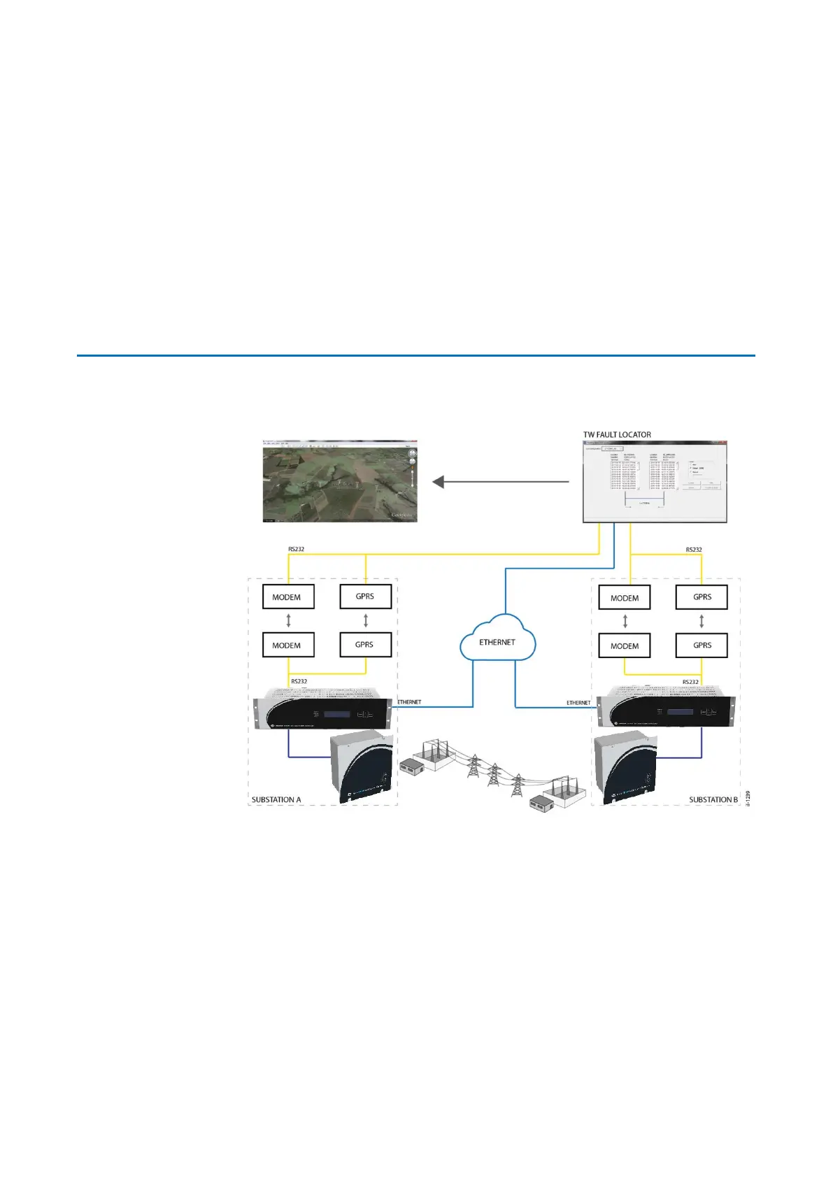
The figure below shows an overview of the Traveling Wave Fault Location
architecture.
Figure 72 – TW Fault Locator architecture overview
Each terminal of the line has to have a set of RPV311 processing unit+RA333
acquisition unit ; and each RPV311 has to be synchronized with a GPS Clock as
accurate as possible. The signal used to extract the traveling waves if the voltage
signal from the secondary circuitry of the VT.
During a fault the RPV311 in each terminal will register the waveform of the traveling
wave in a COMTRADE file, after being triggered by any of the thresholds described in
Chapter 4 - Thresholds.
The COMTRADE files of both ends of the line have to be downloaded to a computer
,where the software TW Fault Locator (present in RPVTools) will run the files and
calculate the distance of the fault. The Chapter Chapter 12: Software – RPV Tools -
TW Fault Locator described the procedure to utilize the software.
 Loading...