Do you have a question about the GE DR60 and is the answer not in the manual?
Provides a functional and technical description and instructions for using the DR60 device.
Identifies professionals involved in installation, commissioning, and operation of the DR60.
Explains special terms, abbreviations, and acronyms used in the manual.
Lists and defines abbreviations used throughout the manual.
Describes the DR60 as a single-box solution for digital recording in power systems.
Provides instructions for carefully unpacking the equipment and checking contents.
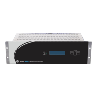
Details external indicators and the DR60 nameplate information.
Highlights the main features of the DR60, including acquisition system and channel capacity.
States that the device has undergone extensive testing and certification.
Explains the DR60's design for substation environments and its recording capabilities.
Lists software packages and their associated licenses used in the DR60.
Emphasizes that personnel must be familiar with safety information before operating the device.
Illustrates and explains common safety symbols used in the manual and on the equipment.
Covers safety aspects related to installation, commissioning, and servicing procedures.
Provides guidance on safely decommissioning and disposing of the equipment.
Details compliance with EMC, LVD, Product Safety, and environmental standards.
Explains the DR60's modular design composed of up to 8 boards.
Describes the physical aspects and layout of the DR60 device.
Details the method used by the DR60 to calculate frequency.
Introduces the IED configuration tool for setting up DR60 functionalities.
Explains the different user access levels (MON, CFG, ADM) and their permissions.
Guides on configuring communication parameters and managing configuration files.
Describes utilities like LOG and Administrative Tools for device management.
Covers parameters for the Physical Device logical node (LPHD).
Details configuration for analog channels, instrument transformers, and sensors.
Explains how to configure physical binary inputs, outputs, and GOOSE inputs.
Covers physical communication ports, datasets, GOOSE, reports, and DNP3.
Details time synchronization methods like IRIG-B and PTP.
Enables and configures waveform, disturbance, SOE, and trend recorders.
Sets thresholds, equations, and matrix for triggering waveform and disturbance recorders.
Details how the DR60 captures voltage and current signals triggered by events.
Explains how consecutive events within a time window are concatenated.
Describes how disturbance records are initiated and the values recorded.
Covers recording minimum, maximum, and average values of RMS and power.
Details the sequence of events recorder for binary inputs, outputs, and GOOSE inputs.
Explains record formats, naming conventions, and storage capacity.
Describes methods for retrieving COMTRADE files using SFTP or DR Manager.
Details the DR60's capability for synchrophasor measurement and transmission.
Specifies the Total Vector Error and accuracy compliance for PMU measurements.
Covers PMU stream port configuration and transmission rates.
Provides steps for quick configuration of the DR60 to transmit PMU data.
Explains TCP/IP and UDP/IP protocols used for PMU data transmission.
Describes Spontaneous and Commanded modes for PMU data communication.
Lists standards for DR60 PMU Class M and P compliance.
Summarizes PMU specifications including streams, protocol, and data types.
Details the Ethernet and serial interfaces available on Slot B.
Lists ports and protocols used by the DR60 web interface.
Explains how to use the DR60 Configurator's scanning tool to find the IP address.
Describes the two primary access methods: DR60 Configurator and Web Interface.
Provides requirements for receiving, unpacking, and caring for the product.
Specifies conditions for maintaining integrity, protection, and user safety.
Covers mechanical installation aspects, including rack mounting options.
Describes wiring types, connections, and pin-out details for installation.
Provides the physical dimensions and weight of the DR60 equipment.
Shows the required panel cutout dimensions for DR60 installation.
Lists available accessories, such as mounting panels.
Details minimal requirements for installing the DR60 Configurator software.
Covers routine checks, in-service, out-of-service, and unscheduled maintenance.
Provides guidance on identifying error conditions and taking corrective actions.
Explains the procedure for updating the DR60 firmware using the Configurator.
Outlines the process for requesting equipment repair services from GE.
Provides safety instructions for GE service personnel performing repairs.
Overview of the technical specifications of the DR60 digital recorder.
Details electrical specifications for power supply options.
Specifies characteristics of electrical and optical Ethernet ports.
Provides specifications for the optical IRIG-B time synchronization input.
Details specifications for RS232/485 serial ports.
Specifies characteristics of the dry-contact relay output.
Details resolution and bandwidth for analog signal acquisition.
Provides detailed specifications for standard and high accuracy voltage inputs.
Specifies characteristics for standard and high accuracy current inputs.
Details specifications for DC voltage and current transducer inputs.
Specifies voltage levels, impedance, and acquisition rate for binary inputs.
Details specifications for digital output channels.
Lists operating temperature, altitude, and humidity requirements.
Summarizes EMC and immunity test results according to IEC standards.
Details safety test compliance according to IEC standards.
Lists environmental test conditions and standards applied.
Provides physical dimensions and weight of the DR60.
Illustrates various wiring configurations for voltage inputs.
Shows different wiring configurations for current inputs.
Contains information on logged events like faults, configuration changes, and alarms.
| Microphone | Built-in |
|---|---|
| Speaker | Built-in |
| PC Connectivity | USB |
| Memory Capacity | 4GB |
| Microphone Type | Omnidirectional |
| Recording Media | Internal Flash Memory |
| Battery Life | Up to 15 hours |
| Playback Features | Variable Speed Playback |