DR60
Digital Recorder
Chapter 3: Design
This chapter provides information about the hardware design of the products.
1 Hardware Architecture
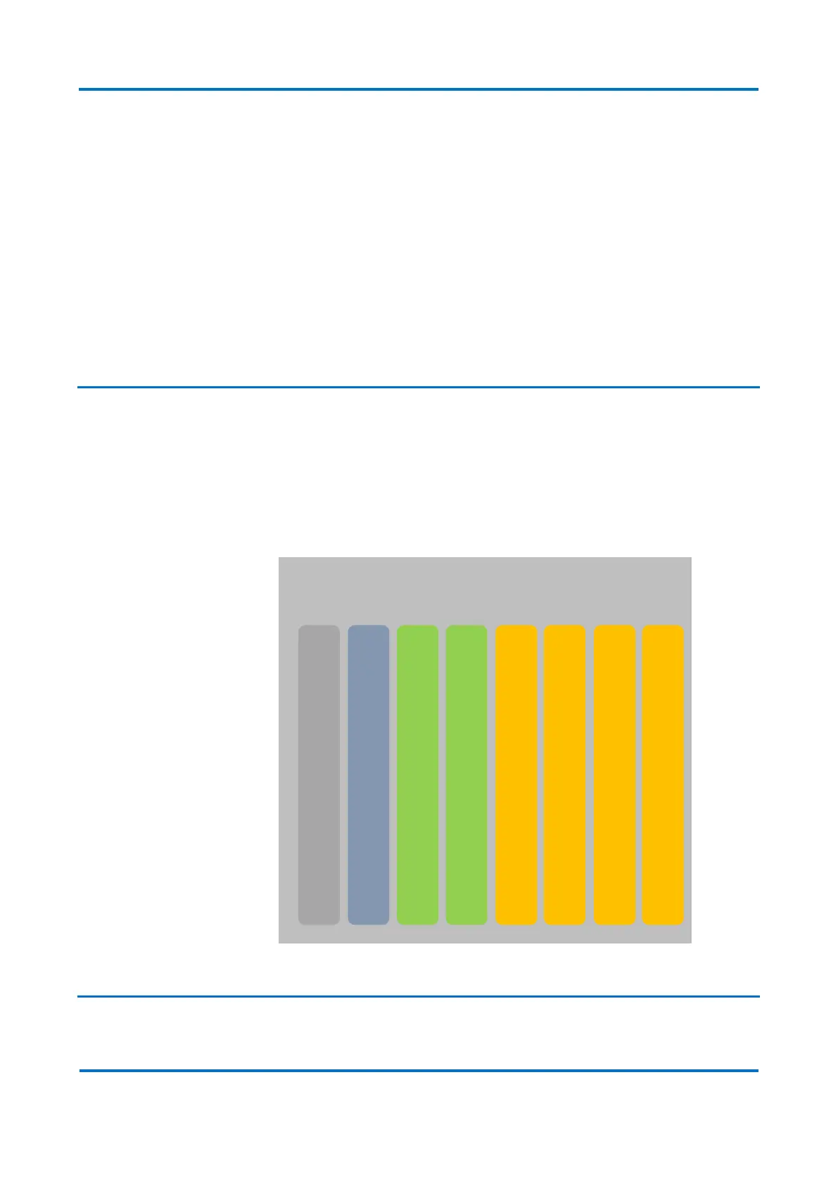
The DR60 is composed of up to 8 boards, from slot A to H. A very flexible number of
inputs and outputs can be achieved by the combination of the boards. The slot A is
reserved for power supply; Slot B for CPU, Ethernet and serial connection and IRIGB
synchronization input; Slots C and D are used for binary input/outputs and slots E to H
can be used either for binary I/O or analog inputs. The figure below illustrates the DR60
slots composition. For the complete list of board option, refer to the ordering option in
Chapter 1.
DR60 slots composition
2 Mechanical Implementation