DR60
Digital Recorder
Chapter 5: Records
This chapter details all types of registers created by the DR60.
1 Wave Form Records
The waveform recorder registers the actual voltage or current signal being applied to
the analog channels. It captures the instantaneous values of the signal at a configurable
sampling rate of 256 or 512 samples/cycle.
The condition that initiated the waveform recording is called trigger. A trigger happens
whenever there’s a violation of digital (binary or GOOSE inputs) or analog thresholds.
Other ways to create waveform records are by cross-trigger signal coming from another
recorder or by a manual trigger.
1.1 Recorded Values
The following values are recorded by the waveform recorder:
• Voltage waveform of all voltage circuits (A, B, C, and N);
• Current waveform of all current circuits (A, B, C, and N);
• Transducer waveform of all transducer channels;
• Binary Inputs
• Binary Outputs
• GOOSE Inputs
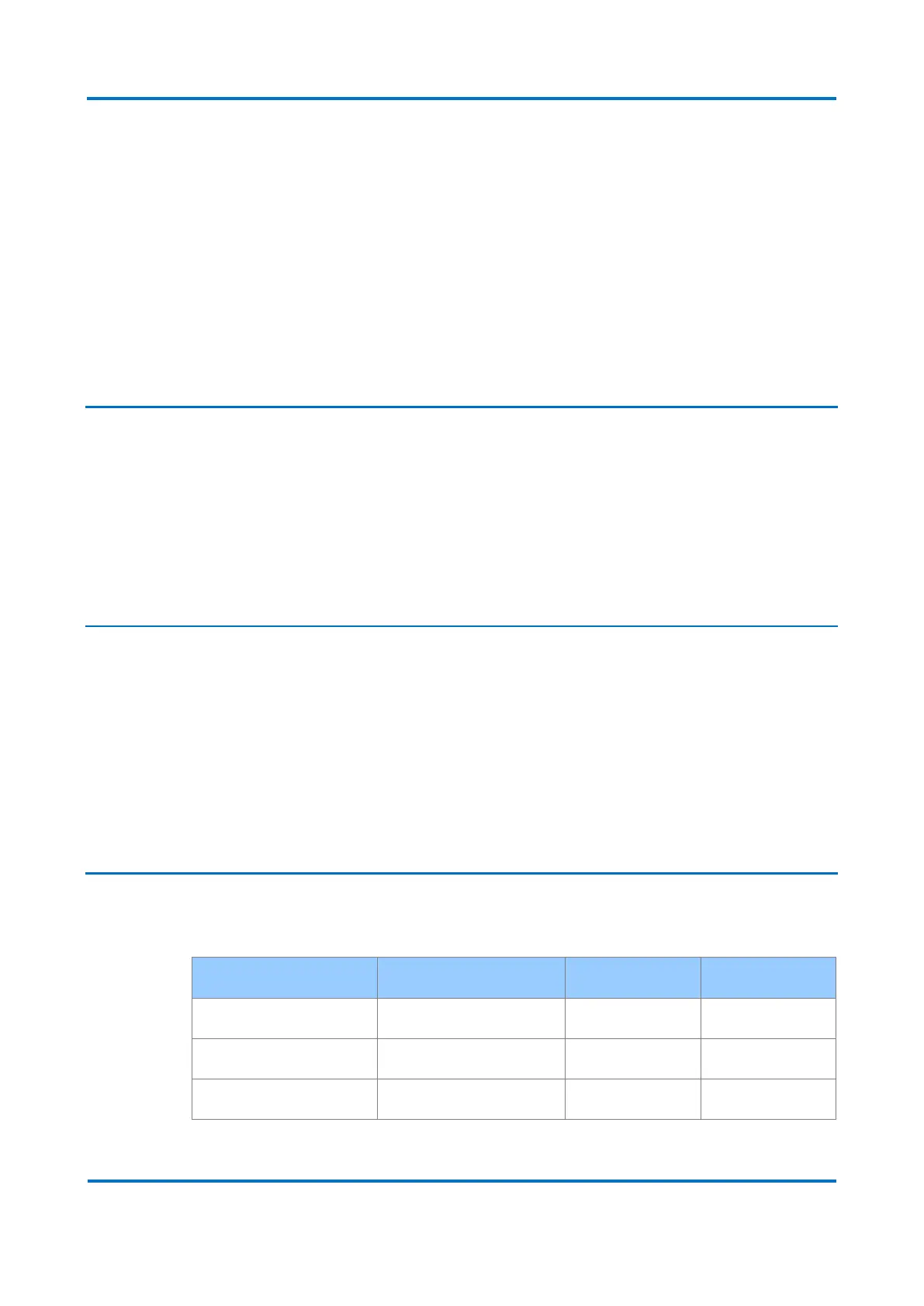
1.2 Recording Times by Trigger
The following durations are configurable in the waveform recorder: