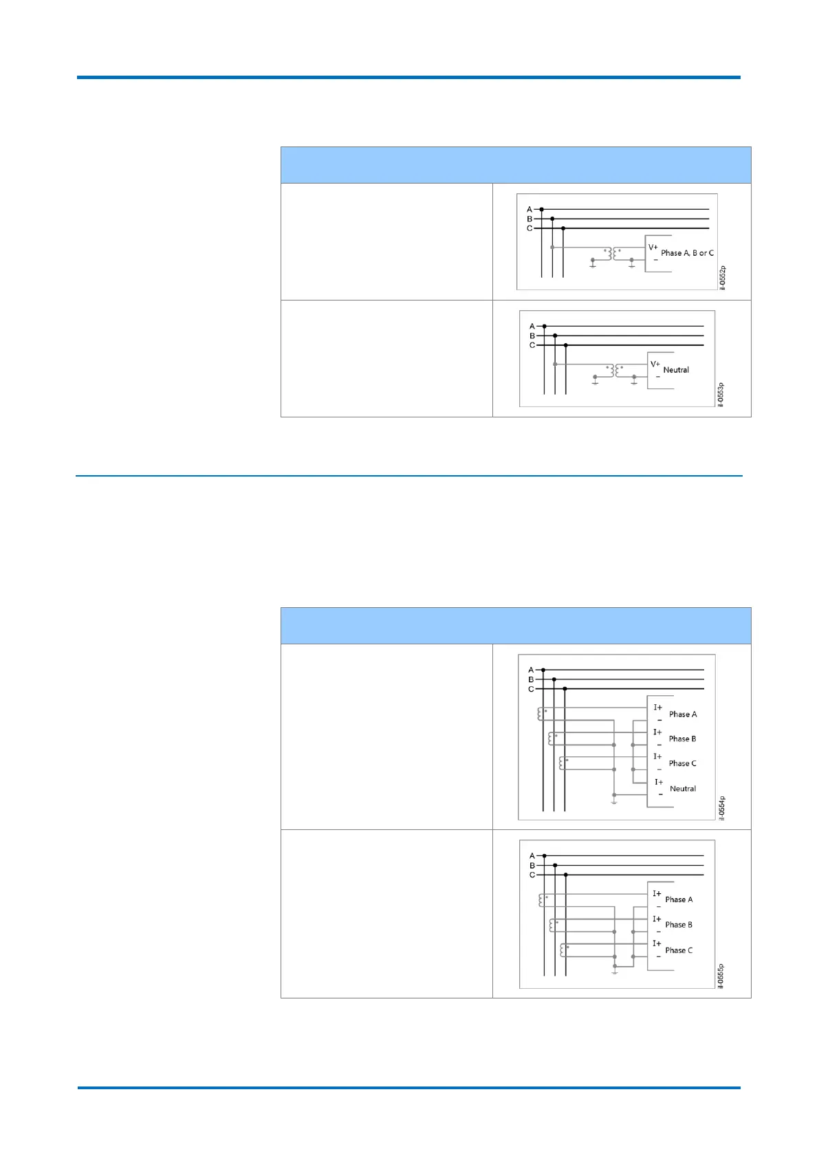
Connection diagram for 1 voltage element connection
1-element connection:
Connection diagram of 1
element (phase A, B or C).
1-element connection:
Connection diagram of 1
element (neutral).
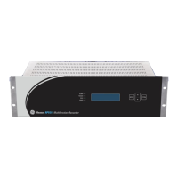
2 Connection Diagrams of the Current Inputs
The DR60 provides the capability for connecting some different current signal
connections for a 3-phase circuit:
Connection diagram of the current inputs
4-element connection: in this
case, the values shown are
equivalent to the voltages of
phases A, B and C, and to the
neutral voltage applied to the
equipment.
3-element (Phases A, B and C)
connection: in this case, the
fourth element is derived of the
values measured by the other
elements. The three elements
are equivalent to the values
applied to the equipment