DIAGNOSTIC STATUS CODES
SX TRANSISTOR CONTROL Page 37
Revised May 2003
TRACTION
STATUS CODE
DESCRIPTION OF STATUS CAUSE OF STATUS INDICATION
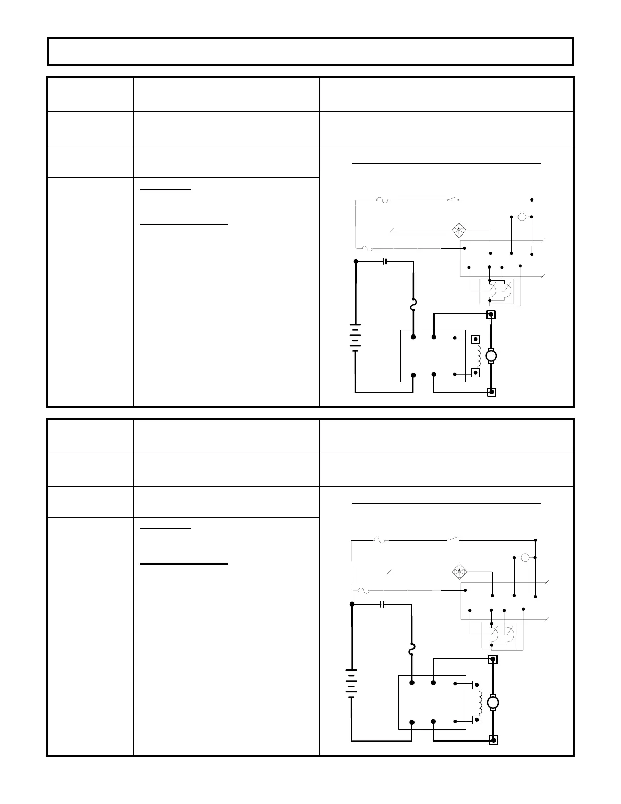
-69
The fan driver current is too high. This status code will be displayed when the current in
the fan driver circuit exceeds its specific current limit.
The control is reset by recycling the key switch.
MEMORY RECALL
YES
CORRECTIVE ACTIONS TROUBLE-SHOOTING DIAGRAM
Circuits valid
for
Traction
Controller
SYMPTOM
Control will not operate.
POSSIBLE CAUSE
· Shorted fan driver coil
· Short between wires connecting to
the fan driver coil.
If the fan driver coil resistance is
correct, then:
· Defective control. Replace
controller unit.
CONTROL POWER
CONNECTION
POS A1 F1
NEG A2 F2
FIELD
ARMATURE
FU1
A2
F2
*
*
*
*
+
-
LINE
*
FU5
*
FU3
KEY SWITCH
*
*
P9
P1
L
P17 P2
*
P18
*
24V
FAN ENABLE
FAN
A1
*
P13
P7
ACCEL
SWITCH
P8
TRACTION
STATUS CODE
DESCRIPTION OF STATUS CAUSE OF STATUS INDICATION
-71
Accelerator potentiometer out of range
(for single accelerator potentiometer
operation).
This status code will be displayed when the voltage at
P7 is greater than 4.13V or less than 0.196V.
MEMORY RECALL
YES
CORRECTIVE ACTIONS TROUBLE-SHOOTING DIAGRAM
Circuits valid
for
Traction
Controller
SYMPTOM
Control will not operate.
POSSIBLE CAUSE
· Defective accelerator pot.
· Measure the voltage from P9 to
NEG. It should be between 4.0 to
4.8V. If it is, replace the
accelerator pot.
· If the voltage from P9 to NEG is not
between 4.0 to 4.8V, remove the wire
from P9 and measure the voltage at
P9. It should be between 4.0 to
4.8V. If it is not, replace the control.
CONTROL POWER
CONNECTION
POS A1 F1
NEG A2 F2
FIELD
ARMATURE
FU1
A2
F2
*
*
*
*
+
-
LINE
*
FU5
*
FU3
KEY SWITCH
*
*
P9
P1
L
P17 P2
*
P18
*
24V
FAN ENABLE
FAN
A1
*
P13
P7
ACCEL
SWITCH
P8

 Loading...


