DIAGNOSTIC STATUS CODES
TRANSISTOR PUMP CONTROL Page 51
Revised May 2003
PUMP STATUS
CODE
DESCRIPTION OF STATUS CAUSE OF STATUS INDICATION
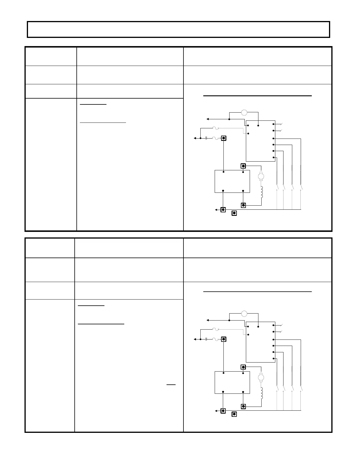
-150
Capacitor volts are low after the line
contactor closes.
This status code will be displayed when the capacitor
voltage is less than 85% of the battery voltage in the run
mode.
MEMORY RECALL
YES
CORRECTIVE ACTIONS TROUBLE-SHOOTING DIAGRAM
Circuits valid
for
Pump
Controller
SYMPTOM
Pump control will not operate.
POSSIBLE CAUSE
Defective line contactor.
· Check for open line contactor power
tips.
Check for loose or open connections in
cables from battery positive to control
positive circuit.
Defective power fuse.
· Check power fuse for open circuit.
No battery voltage at P1.
· Check for battery voltage at POS and
P1.
· Check for loose connection at P1.
PUMP CONTROL
PLUG PL-2
P2
P1
P18
P12
P19
P20
P21
PUMP CONTROL TEMP
P7
L
P17
ACCEL POT INPUT
*
*
*
SPEED 2
SPEED 1
*
SPEED 3
*
SPEED 4
POWER CONNECTION
SUPPLIED BY CUSTOMER
*
KEY SW.
BATT (+)
P
*
FU4
FU2
LINE
CONTACTOR
*
*
ARMATURE
*
FIELD
*
PUMP CONTROL
POWER CONNECTION
A1
A2
A1
A2
A2
A1
P
N
N
BATT (-)
PUMP STATUS
CODE
DESCRIPTION OF STATUS CAUSE OF STATUS INDICATION
-151
Capacitor volts are low before the line
contactor closes. (Internal card
function during precharge)
This status code will be displayed during “key on” when
the capacitor voltage is less than 85% of battery volts
at initial key switch on.
MEMORY RECALL
NO
CORRECTIVE ACTIONS TROUBLE-SHOOTING DIAGRAM
Circuits valid
for
Pump
Controller
SYMPTOM
Pump control will not operate.
POSSIBLE CAUSE
Defective control fuse.
· Check control fuse for open circuit,
replace fuse, if necessary.
Defective control.
· Replace controller unit.
Note: Repeated “charging/discharging” the
capacitors during troubleshooting will cause
status code 51. Also “do not” connect any
loads to the load side of the line contactor.
PUMP CONTROL
PLUG PL-2
P2
P1
P18
P12
P19
P20
P21
PUMP CONTROL TEMP
P7
L
P17
ACCEL POT INPUT
*
*
*
SPEED 2
SPEED 1
*
SPEED 3
*
SPEED 4
POWER CONNECTION
SUPPLIED BY CUSTOMER
*
KEY SW.
BATT (+)
P
*
FU4
FU2
LINE
CONTACTOR
*
*
ARMATURE
*
FIELD
*
PUMP CONTROL
POWER CONNECTION
A1
A2
A1
A2
A2
A1
P
N
N
BATT (-)

 Loading...


