49-2000733 Rev. 1 9
Installation Preparation
INSTALLATION INSTRUCTIONS
POWER SUPPLY
This downdraft vent must be supplied with 120V, 60
Hz. and connected to an individual, properly grounded
branch circuit, protected by a 15- or 20-ampere circuit
breaker or time-delay fuse.
A properly grounded 3-prong receptacle should be
located within reach of the vent’s two-foot power cord.
• Gas Cooktops
If this vent is installed in combination with a GE or
Monogram gas cooktop, it may operate from the same
duplex outlet.
• Electric Cooktops
If this vent is installed in combination with a GE or
Monogram electric cooktop, the vent must operate
from a separate 120V outlet.
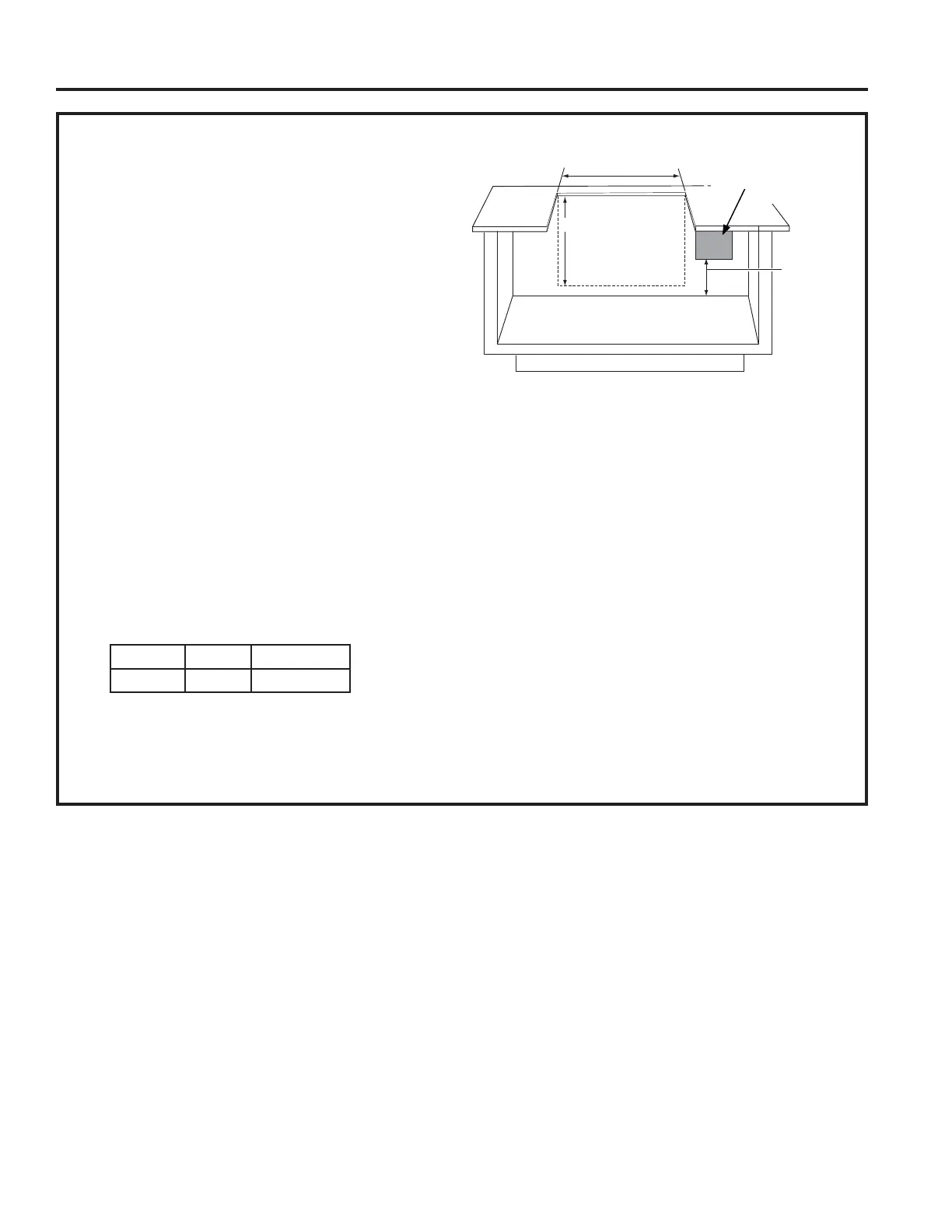
Locate the receptacle inside the cabinet on the right side
wall (see illustration). The receptacle cannot be placed
on the back of the cabinet wall where it may interfere
with the downdraft plenum.
The downdraft vent power cord is to be routed beneath
the cooktop and routed away from heat generated by the
cooktop.
Ensure that the cooktop is installed per manufacturer’s
installation instructions.
IMPORTANT
(Please read carefully)
The power cord of this appliance is equipped with
a three-prong (grounding) plug which mates with a
standard three-prong grounding wall receptacle to
minimize the possibility of electric shock. The customer
should have the wall receptacle and circuit checked by
a qualified electrician to make sure the receptacle is
properly grounded and has correct polarity.
• Where a standard two-prong wall receptacle is
encountered, it is the personal responsibility and
obligation of the customer to have it replaced with a
properly grounded three-prong wall receptacle.
Do not, under any circumstances, cut or remove the
third (ground) prong from the power cord.
Do not use an extension cord or adapter plug with this
appliance. Follow National Electrical Code or prevailing
local codes and ordinances.
Location of Rating Label: on front of chassis of vent
system.
VOLTS AMPS DUCT
120 4.0 3-1/4 X 10
SPECIFICATIONS
DO NOT Locate
Gas or Electrical
Connections within
this Area
34"(cutout width) for 36" models
28-1/2" (cutout width) for 30" models
29-1/2"
12"
Electrical
Outlet 12"
Above
Cabinet
Floor
Locate the gas or electrical
connection only within the
shaded area.