EasyManua.ls Logo

GE WavePro 3200 A - User Manual

GE WavePro 3200 A
26 pages
Print Icon
To Next Page IconTo Next Page
Loading...
WavePro™ Power Circuit Breakers
3200–5000 A Frames, 240–600 Vac
DEH-135 R02
Question and Answer IconNeed help?

Do you have a question about the GE WavePro 3200 A and is the answer not in the manual?

Summary

Chapter 2. Breaker Installation and Removal

2-2 Installing the Breaker

Detailed procedure for installing the draw-out circuit breaker into its compartment.

2-3 Removing the Breaker

Step-by-step instructions for safely removing the draw-out circuit breaker.

2-4 Testing the Breaker

Procedure for testing the breaker's operation without energizing the load.

Chapter 3. Breaker Operation

3-1 Operating Instructions

Guidance on breaker operation, including sequences, manual and electrical charging.

3-3 Breaker Interlocks

Explanation of safety interlocks that prevent improper breaker operation.

3-5 Trip Unit Operation and Setup

Instructions for setting up and operating various trip units for protection.

Chapter 4. Accessory Operation

4-7 Motor Operator (Electrically Operated Breaker)

Operation of the Motor Operator for electrically charging closing springs.

4-8 Remote Close

Operation of the Remote Close accessory for remotely closing the breaker.

Chapter 5. Maintenance

5-1 Inspection

Procedures for performing periodic inspections of the circuit breaker.

Overview

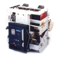
The WavePro™ Power Circuit Breaker is a robust and versatile device designed to protect low-voltage power circuits and equipment. Available in 3200-5000 Ampere frames and suitable for 240–600 Vac applications, these breakers offer advanced protection features and operational flexibility. They are compatible with MicroVersaTrip Plus™, MicroVersaTrip PM™, and Power+™ Trip Units, allowing for tailored protection schemes.

Function Description

The primary function of the WavePro circuit breaker is to interrupt electrical current in the event of an overcurrent, ground fault, or other protective relay function, thereby safeguarding electrical systems and connected equipment from damage. Its draw-out construction is a key feature, enabling rapid replacement of a circuit breaker and facilitating inspection and maintenance without the need to de-energize the entire switchgear. This design is particularly beneficial in GE AKD-10 switchgear, Power Break®, AV-line switchboards, and other manufacturers' equipment using GE OEM substructures.

The breaker's operation involves a sequence of mechanical and electrical actions. It can be manually or electrically charged. Manual charging requires pulling the charging handle down approximately 90 degrees eight times until the springs are fully charged, indicated by a yellow CHARGED background. Electrical charging, available with the optional Motor Operator, involves applying rated voltage to secondary disconnect terminals A8 and A17. A cutoff switch automatically de-energizes the motor once the springs are fully charged. If power is lost during electrical charging, manual cycling of the handle can complete the charging process.

Closing the breaker contacts can be done either by depressing the CLOSE button on the front of the breaker or by energizing the optional Remote Close accessory. An antipump device prevents a second closing operation if the breaker is already tripped OPEN and the closing voltage is maintained, requiring the impulse to be released and reapplied for subsequent closures. A mechanical interlock prevents the closing springs from discharging if an attempt is made to close an already CLOSED breaker.

The breaker is equipped with several safety interlocks to prevent improper operation. The Draw-Out Interlock prevents closing when the breaker is between the CONN (Connected) and TEST positions. A pin on the side of the breaker engages a ramped cam in the switchgear compartment, holding the breaker trip-free when lifted 3/8 inch. An additional interlock keeps the breaker trip-free when the racking handle is engaged. The Contact Interlock prevents the racking handle from engaging the draw-out mechanism racking screw when the breaker contacts are CLOSED, ensuring that the breaker's position cannot be changed while the main contacts are closed. The Spring Discharge Interlock prevents inadvertent discharge of closing springs during maintenance by releasing the springs when the spring discharge lever is pressed during withdrawal from the DISCONNECT position.

Usage Features

The WavePro circuit breaker offers a range of usage features, including various accessories that enhance its functionality and adaptability to different applications.

  • Draw-out Construction: This allows for easy installation and removal of the breaker from its compartment. The process involves lifting the breaker onto rollout rails, pushing it into the compartment to the Disconnect position, and then racking it to the Test or Connected position using a Racking Handle. Removal follows a reverse procedure, ensuring the breaker is open and springs are discharged before withdrawal.
  • Position Indicators: The breaker features indicators for its position (DISC, TEST, CONN) and spring charge status (CHARGED/DISCHARGED), as well as contact status (CLOSED/OPEN), providing clear visual feedback on its operational state.
  • Padlock Provision: This feature allows for securing the breaker in the tripped position using up to three padlocks or scissor-type safety lockout hasps, preventing unauthorized closing.
  • Bell Alarm: Provides remote indication when the breaker has tripped due to a protection trip (overcurrent, ground fault, or protective relay function). It offers normally open and normally closed outputs at the secondary disconnects.
  • Bell Alarm with Lockout: Similar to the Bell Alarm, but prevents reclosing of the breaker after a trip until it is manually reset. This feature requires the breaker to be racked into the connected position for proper lockout function.
  • Shunt Trip: Enables electrical tripping of the breaker from a remote location. An auxiliary switch in series with the shunt trip coil ensures proper operation.
  • Undervoltage Trip Device (Instantaneous): Trips the breaker when its coil is de-energized, typically when the control voltage drops below a specified threshold (30-60% of rated value). Control voltage must be applied for one second before the breaker can be closed.
  • Undervoltage Trip Device with Time Delay: Prevents nuisance tripping on momentary voltage drops by incorporating a time-delay unit (adjustable from 2-6 seconds).
  • Electric Lockout: Uses a coil to prevent the breaker from closing unless the coil is energized, providing an interlocking function, for example, between two breakers. Loss of control voltage does not trip the breaker.
  • Motor Operator: Electrically charges the closing springs, automatically recharging them after the breaker closes if control power is maintained.
  • Remote Close: Allows for remote closing of the circuit breaker after the closing springs have been charged. It includes an antipump feature.
  • Open-Fuse Lockout (OFLO): Used with a Fuse Rollout Element, this accessory trips the breaker to prevent single-phasing if any fuse blows. It indicates which fuse has blown and prevents reclosing until reset.
  • Auxiliary Switches: Provide remote indication of the breaker's main contact position, available in four or seven stages with normally open and normally closed contacts.
  • Hidden-Close Pushbutton: An unmarked replacement for the normal CLOSE button, requiring a stiff rod to engage the mechanism and close the breaker, enhancing security.
  • Push Button Covers: Sealable Lexan® shields that mount over the CLOSE and/or OPEN buttons, preventing accidental or unauthorized operation.

Maintenance Features

Regular inspection and maintenance are crucial for the reliable operation of WavePro circuit breakers.

  • Periodic Inspection: The breaker should be inspected at least once a year, with more frequent inspections recommended under unfavorable conditions (severe load, dust, moisture, high number of operations) or if the load's vital nature warrants it. Inspections should always follow a short circuit or ground fault interruption.
  • Safety Precautions: Before inspection, the breaker must be disconnected from all voltage sources.
  • Operational Checks: During inspection, the breaker should be drawn out to the TEST position. Checks include manually operating the breaker several times to ensure no obstructions or excessive friction, verifying electrical operation of all installed accessories and the motor-charge system, and inspecting the arc chutes and contacts for breakage or excessive burning.
  • Trip Unit Verification: The Trip Unit's proper operation should be checked as described in its respective User Guide (DEH-179 for Power+ Trip Units or DEH-178 for MicroVersaTrip Plus and MicroVersaTrip PM Trip Units).
  • Insulation Inspection: Insulating parts should be checked for signs of overheating or cracks that may indicate thermal aging.
  • Lubrication: Bearing points and sliding surfaces require lubrication with a thin film of GE Lubricant D6A15A1 (Mobil 28) or D6A15A2 (Mobil Temp SHC32). Surfaces should be cleaned with an industry-approved solvent, and excess lubricant removed to prevent dirt accumulation. The contact surfaces of the primary disconnect fingers also need to be cleaned and lubricated. Importantly, breaker contacts, outside diameters of rollers, and the ground radius on the closing prop or trip latch should not be lubricated to avoid dirt and dust accumulation.
  • Documentation: Detailed maintenance procedures and available renewal parts are referenced in DEH-137 and DEF-005, respectively, ensuring comprehensive support for upkeep.

GE WavePro 3200 A Specifications

General IconGeneral
TypeMolded Case Circuit Breaker
Frame Size3200 A
Breaking Capacity65 kA
Trip UnitElectronic
Mounting TypeFixed
Poles3
StandardsUL 489, CSA C22.2 No. 5

Related product manuals