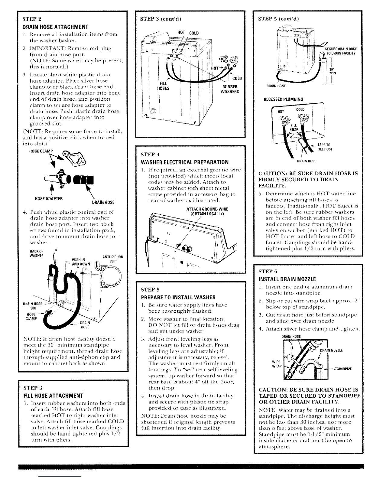
STEP 2
DRAIN HOSEATTACHMENT
1. Remove atl installatio_ items from
the washe_ basket,
2. IMPORTANT: Remove red plug
flora draio hose porL
(NOTE: Some water may be presem,
this is normal.)
3, Locate short white plastic drain
hose adapter, Place sliver hose
clamp over black drain hose end.
Insert drain hose adapter into bent
end ol drain hose, and position
clamp to secure hose adapter to
drain hose. Push plastic d_ai_ hose
damp over hose adapter into
gtooved slou
(NOTE: Requires some I_n'ce m install,
and has a positive click when tinred
into slot,)
HOSEADAPTER
DRAINHOSE
4 Push wtite plastic conicaI end of'
(hair_ bose adapter i*_to washer
drain hose port, Insert two hla_k
screws fom{d m installation pack,
and drive to mount drain hose to
w _sher,
ANTbSIPffON
CLIP
NOTE: If drain hose {acility doesn't
meet the 30" minimum standpipe
height requirement, thread thaii_ hose
through supplied anti-siphon clip and
mount to cabinet back as showm
STEP 3
FILLHOSE ATTACHMENT
1. lnse*t rubber washers i_to both tmds
of each fie hose Attach fill hose
marked }lOT to right washer inlet
valve, Attach fill hose marked CO[[)
to left washer inlet valve. Coupliogs
shoukt be hand-tightened plus 1/2
turn with pliers.
STEP 3 (cont'd)
HOT COLD
FILL
HOSES
U
I
RUBBER
WASHERS
STEP 4
WASHER ELECTRICALPREPARATION
1. if requited, an external grotmd wire
(not provided) which meets local
codes may be added. Attach to
washer cabinet with sheet metal
s(rew proxided in accessory bag to
rear of washer as illustrated.
ATTACHGROUNOWIRE
STEP 5
PREPARETO INSTALLWASHER
I. Be sine water suppl) lines hav{
been thoroughly flushed.
2 Mov( washer to lina! location
DO NOT iet fi[I or drain hoses d,ag
aud get under washer,
:< A@_st front levelirlg legs as
_ecessary to level wash_ r, Flont
leveling legs are adjustable; it
adjustment is necessary, relevel
The washer must rest tirmty on all
Inur legs. I'D *'set" rear selgleveliiig
system, tip _asher forward so that
rear base is about 4" off the floor,
theo drop
4. Instalt drain hose in chain facility
and secure wid_ plastic tic strap
provided or tape as illustrated,
NOTI'h l)rain hose nozzle may be
shorte_*ed if original l_ngtb prevents
full insertion into drain iacility.
= H
STEP 5 (eont'd)
DRAIN HOSE
RECESSEDPLUMBING
V
O_IAIN HOSE
CAUTION: BE SURE DRAIN HOSE IS
FIRMLY SECURED TO DRAIN
FACILITY.
5. Determine which is HOT wate_ line
befi)re Utaching till hoses _o
faucets. Traditionally, HOT t:mcet is
on the/eh. Be st{re rubber washers
are in end of both washer fill hoses
md connect hose fi-om right inlet
valve on washe_ (marked }lOT) to
}lOT faucet a_d left ho_e to COI,D
faucet. Couplings should be hand-
tightened pins 1/2 turn with pliers,
STEP 6
INSTALL DRAIN NOZZLE
I. Itlsert ntm end of a}umintnn drain
nozzle into standpipe
2. Slip o_ cm wu'e wrap back approx. 2"
beIow top o_ standpipe.
3 Cut drain hose just below standpipe
and slide over drain nozzle,
4. Attach silver hose clamp a_{d tighten.
ORAI_ _OSE
W_RE
WRAP
CAUTION: BE SURE DKAIN HOSE IS
TAPED OR SECURED TO STANDPIPE
OR OTHER DRAIN FACILITY°
NOIE: Water may be drained into a
standpipe. The discharge height must
not be less than 30 inches, Ho_ more
than 8 feet above base of washer,
S[a_ dpipe must be I-1/2" minimum
inside diamete_ a_td mnst be {)pen to
almosphere,
I Hill
 Loading...