– 43 –
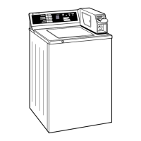
5. Remove the six 10-mm hex-head screws and
washers that hold the stator in place.
Stator
6. Carefully pull the stator away from the outer
tub.
Note: The stator is to be installed with the Hall
sensor towards the back of the outer tub and
located at the 4 o'clock position.
Hall Sensor
• The Hall effect sensor measures the motor rpm.
• Four wires connect the Hall sensor to the main
PCB at connector CN9. (See Control Board
Connections.)
• Resistance can be measured at the Hall sensor
wire connector. The Hall sensor measures
approximately 4.7K Ω between the pink and
blue wires and the pink and red wires, and 9.4K
Ω between the blue and red wires.
• If the sensor has failed, the motor will not
operate.
• The Hall sensor is part of the stator assembly. It
is available as a separate part.
Operation of the motor assembly can be checked
by using service test modes t08 and t09. (See
Service
Mode.)
Specifi c failures associated with the motor assembly
can initiate error codes 9E1, 9E2, 3E1, 3E2, and 3E3.
(See Error Codes.)
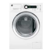
The Hall sensor it is attached to the back of the
stator assembly with 2 Phillips-head screws and
2 small locking tabs. It is necessary to remove the
stator assembly and the 2 Phillips-head screws. The
Hall sensor can then be lifted straight up to release
it from the stator assembly.
Hall Sensor
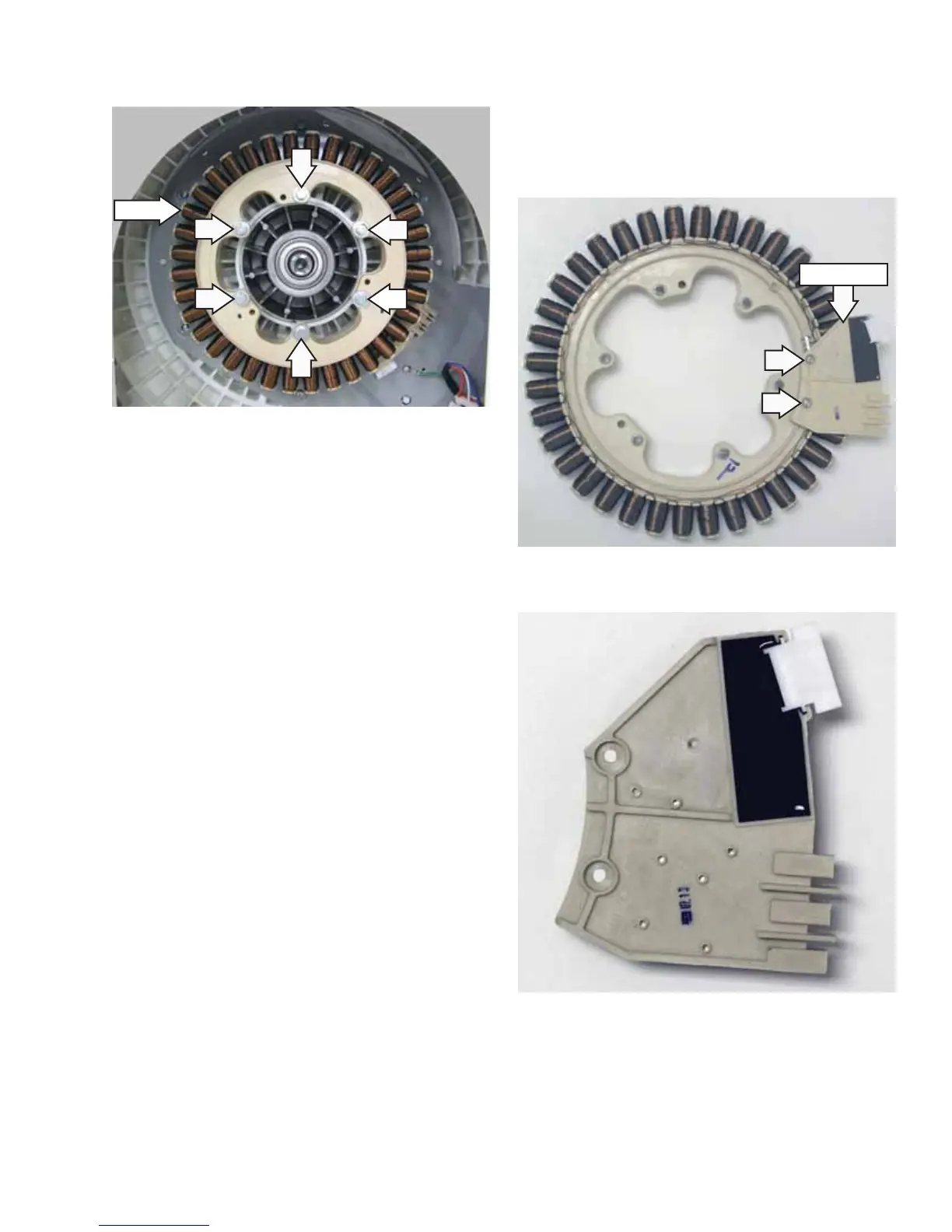
Hall Sensor Removed
 Loading...