EasyManua.ls Logo

GE WR49X10021 User Manual

GE WR49X10021
4 pages
To Next Page IconTo Next Page
Page #1 background imageLoading...
Page #1 background image
Plenum
Disconnect
Light and
Thermostat
522-08W
522-08F
DISCONNECT POWER BEFORE SERVICING TO PREVENT
ELECTRICAL SHOCK HAZARD
IMPORTANT: Follow these instructions completely. Procedure
will vary slightly for non-dispenser models.
Parts Included:
Drain pan assembly with ground wire
Bar of PermaGum
Orange jumper Wire, with female
bullet connector on one end and
stack terminal on opposite end
(not
required on models produced after
10/94).
250ml
squeeze bottle
Insulating styrofoam piece
for side wall
Plastic “Xmas Plug” ratchet
fastener
(not required on models
produced after 10/94).
Insulation pieces to cover entire
evaporator compartment
2 Wire ties
Prepare Freezer Compartment
1. Lift to remove top grille panel frame. Set aside. Locate
and disconnect or cut the 2 drain tube clamps in the
compressor compartment.
2. Remove ice bucket, icemaker, shelves and all materials
in the freezer compartment.
3. Remove the rear
panel section
(plenum). Discon-
nect the wiring to
the light socket
and over-tempera-
ture thermostat if
present.
MONOGRAM FREEZER ICING KIT WR49X10021
INSTALLATION INSTRUCTIONS
522-08J
522-08E
522-08Y
522-08G
522-08D
LEFT
BACK
TOP
FRONT
EVAP ORIFICE
PERF
LINE
RIGHT
EVAPORATOR
PLATE
INSULATION
NOTCH
522-08H
REAR
TOP
FRONT
DRAIN TUBE CLAMPS (2)
COMPRESSOR
COMPARTMENT
DIVIDER
EVAPORATOR
DRAIN
TUBE
522-08L
COMPRESSOR
DRAIN PAN
Installation Instructions Page 1 of 4 70836-00
Question and Answer IconNeed help?

Do you have a question about the GE WR49X10021 and is the answer not in the manual?

GE WR49X10021 Specifications

General IconGeneral
BrandGE
ModelWR49X10021
CategoryFreezer
LanguageEnglish

Summary

Electrical Safety Precaution

Prepare Freezer Compartment

Remove Top Grille and Disconnect Drain Tube Clamps

Remove top grille panel and disconnect drain tube clamps in the compressor compartment.

Empty Freezer Compartment

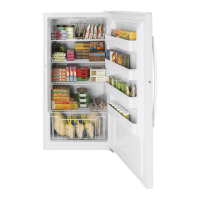
Remove all items like ice bucket, icemaker, and shelves from the freezer compartment.

Remove Rear Panel and Disconnect Wiring

Remove the rear panel section (plenum) and disconnect wiring to light and thermostat.

Evaporator and Insulation Installation

Remove Evaporator Fan Assembly

Remove the evaporator fan/motor bracket assembly and fan support panel.

Remove Drain Pan Heater Assembly

Disconnect drain pan heater leads and remove the drain pan/heater assembly.

Prepare Wiring Harness (TL Models)

For TL Serial models after Oct 1994, insert Xmas fastener plug into pink female lead.

Remove Evaporator

Remove foam, screw, and pull evaporator down from the ceiling.

Prepare Walls for Insulation

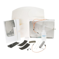
Remove old styrofoam, wipe walls and ceiling dry before installing new insulation.

Apply Insulation to Walls and Ceiling

Press insulation pieces onto right, left, rear, and front walls, then the ceiling.

Trim Insulation for Model Size

Trim insulation pieces for 36" and 42" models; 48" models use full size.

Install Front Corner Foam Piece

Position new foam piece flush with ceiling and front wall in the front inside corner.

Notch Evaporator Header Plate

Cut a notch in the evaporator header plate bottom corner for drain pan fit.

Evaporator Reassembly and Sealing

Install Left Side Evaporator Insulation

Press insulation onto left side top, front, and rear plates; open eyelet slot.

Reinstall and Secure Evaporator

Reinstall evaporator screw, push up, engage eyelet screw, tighten, and replace foam block.

Maintain Evaporator Coil Clearance

Ensure 3/16" clearance between evaporator coils and right side styrofoam to prevent moisture.

Seal Heat Exchanger and Grommet

Check and seal heat exchanger entry, wire grommet with PermaGum for a complete seal.

Prepare Drain Pan Hose

Cut drain pan hose to length for 36" and 42" wide models; 48" models use full length.

Insert New Drain Hose

Insert the new drain hose through the evaporator compartment wall into the machine compartment.

Align Drain Pan Assembly

Align drain pan assembly against the evaporator bottom, sealing with insulated tape.

Secure Drain Hose and Ground Wire

Secure drain hose with original clamps and ground wire to the freezer cabinet.

Connect Evaporator Fan Wiring

Connect orange wire from evaporator fan motor to stack terminal of orange jumper wire.

Connect Drain Pan Heater Wiring

Connect drain pan heater leads to yellow harness and orange jumper wire connectors.

Final Installation Checks

Install Evaporator Fan Support Insulation

Install insulation on the back of the evaporator fan support, trim if needed, and reinstall panel.

Test Drain Pan Flow

Pour water onto evaporator to check if it flows into the compressor drain pan.

Reinstall Evaporator Fan/Motor Assembly

Reinstall the evaporator fan/motor assembly, checking for proper rotation and clearance.

Reinstall Rear Panel and Icemaker

Reinstall the freezer rear panel (plenum) and icemaker, ensuring fill tube alignment.

Reinstall Light Shield or Ice Bucket

Reinstall the light shield or ice bucket, depending on the specific freezer model.

Perform Final Installation Checks

Check seals, drain tube, connect power, install grille, set temp, and verify fan operation.

Related product manuals