– 28 –
A0: #&
\TRWP]XRP[
\P]dP[
RWP]VT^eTa
cWTa\^bcPc
aT`dXaX]V%
R^]]TRcX^]fXaTb
A0: #'3
b^[XSbcPcTSXVXcP[
\P]dP[
RWP]VT^eTa
cWTa\^bcPc
aT`dXaX]V%
R^]]TRcX^]fXaTb
A0: #'?
b^[XSbcPcTSXVXcP[
_a^VaP\\PQ[T
Pdc^RWP]VT^eTa
cWTa\^bcPc
aT`dXaX]V%
R^]]TRcX^]fXaTb
The temperature boost option should not be used
with the remote thermostat operation since this will
cause the unit to switch to resistance heat when
outdoor temperatures are below 46ºF.
5TPcdaT 7TPc?d\_
8]S^^a5a^bc2^]ca^[ HTb
5aTTiTBT]cX]T[ HTb
0dc^5P]B_TTS =^
4[TRca^]XRCT\_TaPcdaT;X\XcX]V =^
BfXcRWc^ATbXbcP]RT7TPc1PbTS
>]8]S^^aCT\_TaPcdaT
3TcTa\X]TSQhAT\^cT
CWTa\^bcPc
BfXcRWc^ATbXbcP]RT7TPc1PbTS
>]>dcS^^aCT\_TaPcdaT
HTb
ATeTabT2hR[T3TUa^bc HTb
BX\d[cP]T^dbATbXbcP]RT7TPc
fXcW7TPc?d\_
=^
ATbXbcP]RT7TPc;^RZ^dc HTb
|B\Pac5P]}5P]2hR[T
5P]>=0DC>BTc>]
AT\^cTCWTa\^bcPc
2T]caP[3TbZ2^]ca^[ HTb
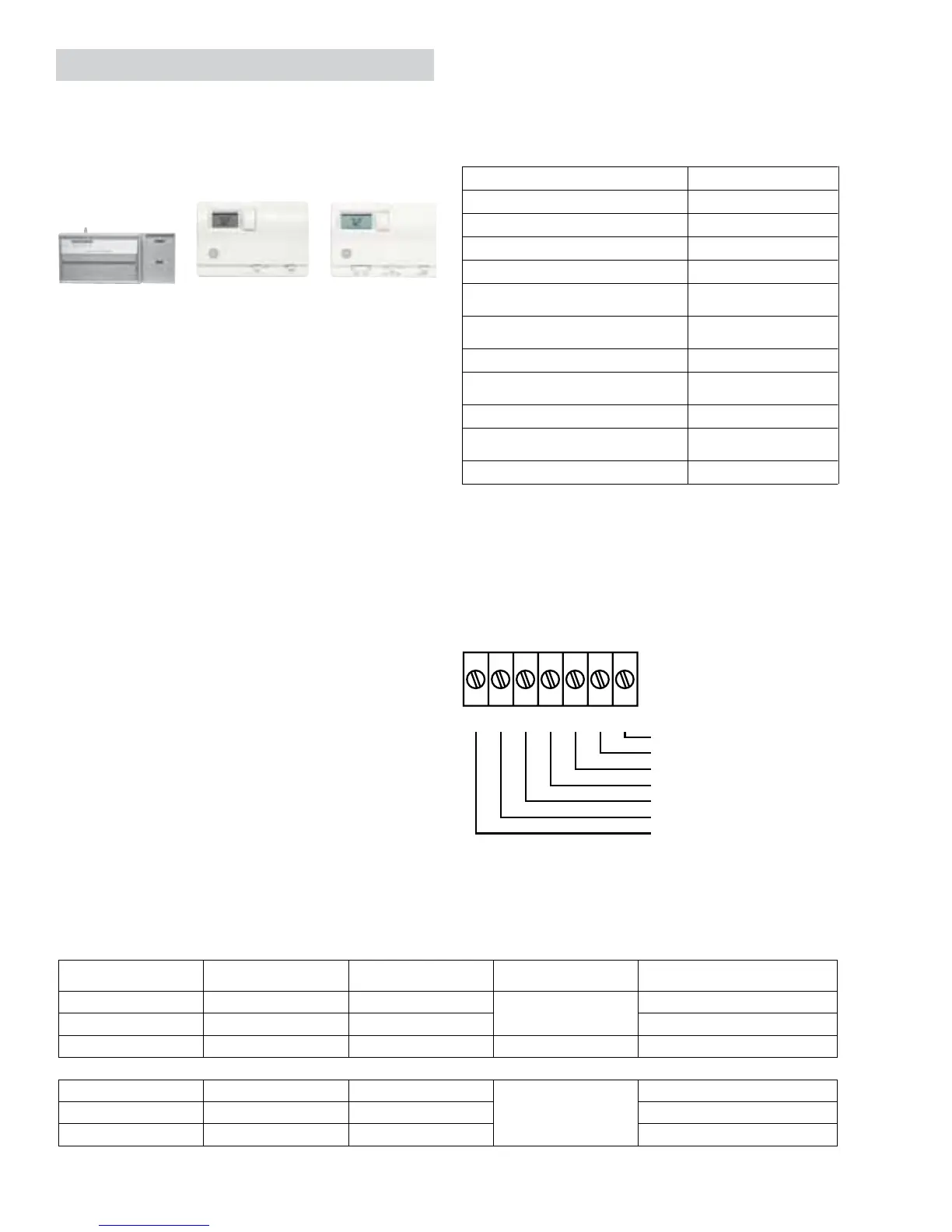
5XT[SFXaX]VCTa\X]P[
A !#E02 6; ;^fB_TTS5P]
67 7XVWB_TTS5P] 1 ATeTabX]VEP[eT
H 2^\_aTbb^a F 7TPcTa
2 2^\\^]6a^d]S 2 6]S
2
',
'(
"
9
7
#
#OMMON'ROUND
7HITE(EATER
9ELLOW#OMPRESSOR
"LACK2EVERSING6ALVE
'REEN(IGH3PEED&AN
'REEN,OW3PEED&AN
2ED6!#
I^]T[X]TBTaXTb CWTa\^bcPc<^ST[ Ch_T 5d]RcX^] ;^fE^[cPVT2^]SdRc^ab
!' A0: %"0 <TRWP]XRP[
2^^[X]VP]S7TPcX]V
#
A0: %#3 3XVXcP[ $
A0: %#? 3XVXcP[ ?a^VaP\\PQ[T $
"' A0: #& <TRWP]XRP[
BX]V[TBcPVT2^^[X]V
!BcPVT7TPcX]V
%
A0: #'3 3XVXcP[ %
A0: #'? 3XVXcP[?a^VaP\\PQ[T %
CWTa\^bcPcfXaTbXiTd_c^%UTTc0F6!d_c^%%UTTc0F6 '
Remote Thermostat Control Selection Chart For Zoneline Packaged Terminal Units
The control voltage on the remote control
conductors is 24 VAC.
The class 2 mode switch, dip switch #4 on the
auxiliary control board on the 3800 series, must be
set to the ON/UP mode to enable remote thermostat
control. Refer to installation instructions packaged
with the chassis.
The fan speed for the 3800 series in remote
thermostat operation is selected by the connection
of the fan wire from the thermostat to either the
HIGH or LOW terminal on the unit. See the sketch of
the unit terminals for the location of the HIGH and
LOW fan speed terminals. Operating the unit in low
fan speed reduces the operating sound level of the
unit.
When connected to a remote thermostat, the indoor
air temperature sensing is shifted from the unit to
the remote thermostat. For this reason, the units
will operate slightly different when connected to
a remote thermostat. The following chart shows
the unit operation when connected to a remote
thermostat.
Heat Pump Models
The Zoneline 3800 series heat pump units may
be connected to a single stage cooling/two stage
heating thermostat designed for use with heat
pump systems. GE offers 3 thermostats compatible
with the 3800 series units.
 Loading...