09900-03.2014-DGbF
Bock LR Leistungsregler
Bock LR Capacity regulation
Bock LR Régulation de puissance
1
Sehr geehrter Kunde,
der Bock-LR-Leistungsregler ist ein hochwertiges,
zuverlässiges und servicefreundliches Qualitäts-
produkt aus der Bock-Zubehörfamilie. Um die
Vorteile der efzienten Leistungsregelung in vollem
Umfang und über den gesamten Einsatzzeitraum
Ihrer Kälteanlage nutzen zu können, beachten
Sie unbedingt die folgenden Installations- und
Wartungshinweise. Bei Fragen zu Montage und
Betrieb des Gerätes wenden Sie sich bitte an
unsere Abt. Anwendungstechnik oder an den
Kältefachgroßhandel bzw. unsere Vertretungen. Das
Bock-Serviceteam erreichen Sie telefonisch über
unsere kostenlose Hotline 00 800 / 800 000 88
oder via E-Mail: bock@gea.com
1 Erläuterung
Ein Kältemittelverdichter wird generell auf die
benötigte Maximal-Kälteleistung der Anlage ausge-
legt. Schwankender Kältebedarf jedoch macht es
nötig und wirtschaftlich sinnvoll, dass die Verdich-
terleistung dem aktuellen Kältebedarf angepasst
wird. Dies geschieht mit einer Leistungsregelung.
1.1 Methoden der Leistungsregelung
Wir bieten verschiedene Systeme der Leistungsre-
gelung an. Ihre Wahl wird bestimmt durch die Art
der Anlage und den Verdichtertyp. Kombinationen
verschiedener Systeme sind möglich.
1.1.1 Mechanische Leistungsregelung
Sauggasabsperrung mittels Magnetventil (Zylin-
derabschaltung), wobei der Sauggasstrom im
Zylinderpaar abgesperrt wird.
1.1.2 Elektronische Leistungregelung
Stufenlose Drehzahlregelung über Frequenzum-
richter.
Diese Druckschrift behandelt die elektro-
mechanische Leistungsregelung durch Saug-
gasabsperrung (Zylinderbankabschaltung).
Dear customer,
the Bock LT capacity regulator is a top grade,
reliable, service-friendly quality product from
Bock‘s accessories range. In order to make full use
of the advantages of efcient capacity regulation
throughout the entire service life of your refrigera-
ting plant, it is important that you observe the fol-
lowing installation and maintenance instructions.
If you have any questions about installation and
operation of the unit, simply contact our technical
customer service department or your refrigera-
ting wholesaler or our representatives.
The Bock
service team can be contacted by phone with
a toll-free hotline 00 800 / 800 000 88 or via
e-mail: bock@gea.com
1 Explaination
A refrigeration compressor is generally rated accor-
ding to the maximum referigeration duty of the plant.
However, uctuating refrigerating requirements
make it necessary and economically rational for the
compressor capacity to be adjusted to the current
cooling requirements.
1.1 Methods of capacity regulation
We offer various systems for capacity regulation.
Their choice depends on the kind of plant and type
of compressor concerned. Combinations of different
system are possible.
1.1.1 Mechanical capacity regulation
By suction gas shut-off system (cylinder shut-down),
whereby the suction gas current can be shut off for
pairs of cylinders.
1.1.2 Electric capacity regulation
With full variable speed control by means of fre-
quency converter.
This leaet deals with electro-mechanical capa-
city regulation by means of suction gas shut-off
systems (cylinder bank shut-down).
Cher Client,
le régulateur de puissance LR de Bock est un produit
de très grande qualité, able et d‘un service facile
faisant partie de la famille des accessoires Bock.
An de pouvoir proter pleinement des avantages
de la régulation de puissance efciente et de pouvoir
utiliser toute la durée d‘application de votre installa-
tion frigorique, veuillez impérativement suivre les
notices d‘installation et de maintenance suivantes. Si
vous avez des questions concernant le montage et le
fonctionnement de l‘appareil, veuillez vous adresser à
notre Service Technique d‘Application ou au commerce
de gros de la réfrigération, voire à notre représentation.
Vous pouvez contacter l‘équipe du service Bock
par téléphone gratuite à 00 800 / 800 000 88
ou par e-mail: bock@gea.com
1 Explication
En rèle générale, un compresseur frigorique est concu
pour la puissance frigorique maximale requise de I‘
installation. Toutefois la demande de froid irrégulière
rend nécessaire et judicieux du point de vue écono-
mique, d‘adapter la puissance du compresseur à la
demande de froid du moment. Ceci est réalisé par la
régulation de puissance.
1.1 Méthodes de régulation de puissance
Nous offrons différents systèmes de régulation
de puissance. Leur choix sera guidé par le genre
d‘installation et le modèle de compresseur. II est
possible de combiner divers systèmes.
1.1.1 Régulation mécanique de puissance
Par arrêt de gaz d‘ aspiration (mise hors circuit des
cylindres). Le courant de gaz d‘aspiration pouvant être
arrêté dans les paires de cylindres.
1.1.2 Régulation électronique de puissance
Par régulation continue de la vitesse par un changeur
de fréquence.
Cet imprimé traite la régulation électro-mécanique
de puissance par I‘arrêt de gaz d‘aspiration (mise
hors circuit des cylindres).
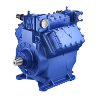
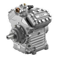
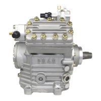
Beispiel/Example/Exemple :
Fahrzeugverdichter FK50
mit zwei Leistungsreglern
Vehicle compressor FK50
with two capacity regulators
Compresseur automobile FK50
à deux régulateurs de puissance