This document is an operation manual for the Gecko CS/ES6000Y Series and Gecko Y Series spa control systems, including models 6330Y, 6338Y, 6339Y, EP2000, and EP2001. It provides detailed information on electrical installation, heater setup, power connections, circuit board configurations, pump cord connections, Wi-Fi module installation, spaside control installation, spaside functions and features, power-up and breaker settings, low-level program configuration, spaside messages, system plug pinouts, operation considerations, troubleshooting, and warranty information.
Function Description:
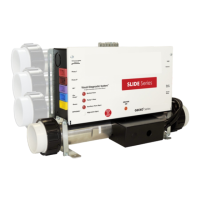
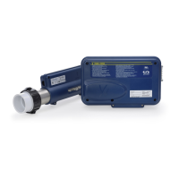
The Gecko CS/ES6000Y and Y Series are advanced control systems designed for spas and hot tubs. They manage various components such as pumps, blowers, heaters, lights, and ozone generators to provide a comfortable and customizable spa experience. The system features a Visual Diagnostic System™ with indicator lights for key components and statuses like Pump 1, Pump 2, Air, Circ Pump, Ozone, Auxiliary Fuse, High-Limit, System Fuse, Light, and Sensors. Some models are Wi-Fi enabled, allowing for remote control via a mobile application. The systems support different heater configurations, including "Fixed," "Slide," and "Versi-Heat," to accommodate various plumbing arrangements and installation needs.
Important Technical Specifications:
- Heater Configurations:
- -U Series ("Fixed" Heater): Designed for the most common heater position. May require plumbing modification for proper alignment depending on the replaced control.
- -US Series ("Slide" Heater): Allows heater positioning within 20" of the control for minimal plumbing modifications.
- -VH Series ("Versi-Heat" Heater): Allows heater positioning within 60" of the control for installations with limited equipment area, minimizing plumbing modifications. Versi-Heat heaters are pressure switch controlled and must be installed on the pressure side of the pump. They require a minimum flow of 18 GPM through the heater.
- -LH Series ("Less Heater"): Allows customer-supplied custom heater configurations. Specific wiring connections and details are covered in a separate "LH" wiring diagram.
- Electrical Service Requirements:
- Voltage: Convertible between 240-VOLT (4-Wire) and 120-VOLT. Some models are 240-VOLT ONLY (3-Wire/Export).
- Amperage: Varies by model and configuration. The System Data Label provides specific equipment voltage and maximum amperage draws.
- Wiring: Requires copper conductors only, sized according to NEC Table 250-122 for ground and Table 310-16 for power conductors.
- GFCI (Ground Fault Circuit Interrupter): Mandatory electrical safety device. Can be installed in the main service panel or a separate sub-panel. Load neutral must be connected directly to the GFCI.
- Bonding: A bonding lug is provided on the control box for connection to local ground points with a solid copper bonding conductor.
- Disconnect: NEC and local codes require a "disconnect" within "line-of-site" of the spa.
- Circuit Board Configurations: All component outputs are pre-configured for 120V but can be converted to 240V using the provided wiring diagram and Voltage Selection Chart.
- Voltage Selection Chart for 240V Conversion:
- P1 2-SPD: 240V, 12A, Red wire, From N to L2
- P2 1 or 2-SPD: 240V, 12A, Violet wire, From N to L2
- Blower: 240V, 8A, Blue wire, From N to L2
- Ozone: 240V, 1A, Yellow wire, From N to L2
- Circ Pump: 240V, 2A, Brown wire, From N to L2
- Important: Circulation Pump & Ozone must be the same voltage rating.
- Pump Cord Connections:
- 2-Speed Pump: Black (High Speed), Red (Low Speed), White (Common), Green (Ground).
- Single Speed Pump/Accessory: Black (Hot/Line), White (Common), Green (Ground).
- Wi-Fi Module (Optional): PT# 34-0216G. Connects to the system circuit board via "CO" port and to a Wi-Fi router via "EN" module. Status light indicators for pairing mode, controller/router detection, and server detection.
- Spaside Control (K35): Cut opening of 2.625" x 6.375" (67.36 mm x 161.92 mm). Connects to PCB connection marked C1.
Usage Features:
- Spaside Control (CS633X): Features buttons for Power, Program, Temp Up, Temp Down, Pump 1, Pump 2, Blower/Pump 3, and Light.
- Pump 1: Press once for low speed, second time for high speed (dual-speed pump), third time turns off. Built-in 20-minute timer. Indicator flashes for low speed.
- Pump 2: Press once for on, second time for off (unless two-speed pump, then Low, High, Off). Built-in 20-minute timer.
- Blower Key: Press once for on, second time for off. Built-in 20-minute timer.
- Light: Press once for on, second time for off. Built-in 2-hour timer.
- Temp Up/Down: Adjusts temperature set point. Display shows desired temperature, not current water temperature.
- Programming Options (K8 Keypad):
- Power Key: Accesses Manual Economy Mode (maintains temperature 20°F less than set point). "Eco" indicates active, "nEc" indicates not active.
- FILTER/PROGRAM Key: Short press displays clock. Long press (5 seconds) enters program menu to set clock, filter cycles, purge cycles, economy mode, and temperature units. Changes are saved after confirming the last parameter. System exits program menu without saving after 10 seconds of no key press.
- Setting the Clock: Adjust hours and minutes using UP/DOWN keys.
- Setting the Filter Cycle: Adjust filter start time (F5##) and duration (Fd##) in hours. 0 = No Filtration, 24 = Continuous Filtration.
- Setting the Filter Cycle Frequency: Adjust number of cycles per day (FF##, 1-4 cycles).
- Setting the Economy Mode: Enable/disable economy program (EP##, 1=On, 0=Off).
- Setting the Economy Start Time: Set hour the economy cycle starts (ES##).
- Setting the Economy Duration: Set active time in hours (Ed##). 0 = No Economy, 24 = Continuous Economy.
- Changing Temperature Readout: Switch between Fahrenheit (F) and Celsius (C).
- Power-Up & Breaker Setting:
- Boot-up Sequence: Lamp test, software number, software revision, low-level selection.
- Breaker Setting: Important for safe current management. Access menu by holding Filter button. Use Up/Down to select value (10-48 AMP), then Filter to set. Typical settings (b) for GFCI ratings are provided (e.g., 60 Amp = 48Amp, 50Amp = 40Amp).
- Changing Low-Level Program Configuration: For servicing or replacing units, re-enter programming by holding Pump 1 key for 30 seconds until L## is displayed. Use Temp Up/Down to choose configuration number, then Filter to confirm.
- Low-Level Configuration Number Chart:
- 6330: 13* (Default), 2 SPD, 2 SPD, 1 SPD, NO (No Circ Pump)
- 6330 w/CP: 14, 2 SPD, 2 SPD, 1 SPD, YES (Always on Circ Pump)
- Smart Winter Mode: Automatically turns on pumps to prevent freezing in pipes when risk is detected. Remains active for 24 hours after risk subsides. Indicator light illuminates when active.
Maintenance Features:
- Filtration System: Refer to the Spa Manufacturer's Owner's Manual for operation, maintenance, and cleaning. Heater pump requires a minimum flow of 23 GPM through the heater.
- Chemical Water Treatment: Maintain proper water chemistry (pH, total alkalinity, total hardness) to prevent corrosion, mineral deposits, and ensure sanitizer effectiveness. Avoid using softened water.
- Troubleshooting: Comprehensive list of common problems and solutions, including:
- Nothing Operates: Check main breaker, sub-panel breaker, GFCI, power switch, component connections, power cord, and for over/high temperature protection messages.
- No, Low or Surging Water Flow: Check for air lock, restricted flow (open valves, clear suction fittings), dirty filter, low water level.
- Low Speed Pump Not Operational: Check circuit board configuration, pump connection, blown fuse.
- Jets or Blower Not Operational: Check blower/pump connection, blown fuse, over/high temperature protection messages.
- Therapy Jet Not Operational: Check water shut-off valves, dirty filter, jet adjustments, diverter valve adjustments, thermal overload tripping.
- Water Leaks: Check spa overfill, too many people, drain-valve, couplings/unions, pump seal, plumbing connections, spaside control, air blower plumbing.
- No Heat: Check temperature set point, over/high temperature protection, current limiting (120V systems won't heat if high speed or blower is on), power (reset breaker), low water flow, system mode.
- Light Not Operational: Check light bulb, reflector, light connection.
- High Heat: Check filter cycles (running too long), temperature set point (too high), high ambient temperature (remove spa cover).
- GFCI Breaker Trips Occasionally: May be due to lightning/electrical storm or power surge (reset GFCI).
- GFCI Breaker Trips Immediately: May indicate defective component, improper GFCI installation, or disconnected Temp/Hi-Limit sensor (connect to P38 on PCB).
- System Data Label: Located on the control box, provides essential information for warranty and service, including order code, product, serial, code, volts, amps, and model.