7
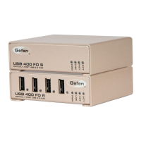
RECEIVER UNIT PANEL DESCRIPTIONS
1 Port (USB Type A)
USB device input port
2 Device LED (Green/Orange)
Indicates when a USB device is connected to the Device Port. Solid green
when device is plugged in and active. Off when device is in a suspend mode
or Receiver unit is powered off. Orange when the Receiver unit detects an
overcurrent condition, or if the attached USB device attempts to draw more than
the 500mA current.
3 Power LED (Blue)
LED turns on when power is supplied. Off when no power is supplied.
4 Link LED (Green)
Indicates a valid ExtremeUSB® link is established between
the Sender and Receiver
5 Host LED (Green)
Indicates that the USB-400FO system is properly enumerated on the host PC.
LED blinks when in suspend mode.
6 Activity LED (Amber)
Indicates activity when data transmission is active between the Sender and
Receiver. LED blinks intermittently with or without a USB device plugged in.
When the Sender and Receiver are in a suspend mode, the LED is off.
7 Grounding point
Optional Earth Ground connection to housing of unit.
Accepts an M2 type screw.
8 Power port
Connects to the 5V DC power supply.
Required for proper operation.
9 Link Port (Duplex LC)
Extension link Duplex LC fi ber optic transceiver port.
 Loading...