41
80290C_MHW_2400_0908_ENG
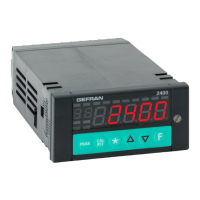
5 • TECHNICAL SPECIFICATIONS
This section contains a list of the Technical Specifications for the instrument 2400.
Display 1 x 5 red/green bicolor digits, height 13mm
1 x 2 red digits, height 7mm
14 x red led
Keys 6 mechanical keys (Peak, Cal/Rst,
*
, INC, DEC, F)
Accuracy 0.1% f.s. ±1 at 25°C room temperature
Thermal drift < 150ppm/°C on f.s. for current/voltage and strain-gauge inputs
IN1, IN2 main input/s Strain-gauge: 350Ω, sensibility 1,5...4mV/V,
with probe power supply 5/10Vdc ±5%
Potentiometer: ≥ 100Ω, Ri > 10MΩ @ 2,5Vdc
Linear DC: ± 60mV, ± 100mV, ± 1V, ± 5V, ± 10V, Ri > 10MΩ
0/4...20mA, Ri = 50Ω
TC, RTD
Sampling time 2msec
TC type (Thermocouples) (ITS90) J, K, R, S, T (IEC 584-1, CEI EN 60584-1,60584-2)
a 64 segment custom linearization can be inserted
Cold junction error 0,1°C / °C
RTD type (Temperature resistance) (ITS90) Pt100 (DIN 43760),
Max. line resistance for RTD 20Ω
Safety Detection of short-circuit or opening of probes,
no probe power; LBA alarm
IN3, IN4 auxiliary inputs Potentiometer: 1...10KΩ, @ 10Vdc
Linear DC: 10V, Ri > 2MΩ
0/4...20mA, Ri = 50Ω
Sampling time 10ms
Linear scale ranges -19999...99999, with configurable decimal point position
Type of relay contact NO (NC) 5A, 250V/30Vdc cosϕ = 1
OUT 1, OUT 2, OUT 3, OUT 4 outputs
Logic output 24Vdc, > 18V at 20mA, source / sink type
OUT 1, OUT 2, OUT 3, OUT 4 outputs Ru = 390Ω
Relay / logic outputs with MD8 OUT3, …, OUT 10 The outputs are assigned to the state of alarms AL3,...,AL10
Refresh every 2ms.
Digital inputs Isolation 1500V, sampling time 60ms
DI1, DI2 24Vdc, 5mA (PNP) or by voltage-free contact (NPN) max 5mA
select PNP/NPN via configuration parameter
OUT W analog retransmission Continuous, resolution improved by 0,03%, isolation 1500V
refresh every 2msec in sync with sampling of variables IN1 and IN2
0/2...10V, ± 10V max 25mA, short-circuit protection
0/4...20mA, max load 500Ω
Max power limit -100.0 ... 100.0%
Fault power setting Maintains PV value display
Configurable alarms Up to 3 alarm functions assignable to an output and configurable of
type: maximum, minimum, symmetrical, absolute, relative, LBA
for AL1, AL2 calculation every 2ms in sync with sampling of variables
IN1 and IN2,
For AL3, …, AL 10 calculation every 2…4 ms, depending on number of alarms
Alarm masking Exclusion during warm up, memory, reset from faceplate and/or contact
Probe power supply 5Vdc, 10Vdc, for strain-gauge probes, max 200mA
1,2Vdc for potentiometers ≥ 100Ω
Transmitter power supply 24Vdc ±5%, max 100mA
Serial interface RS485 isolation 1500V
Baudrate 1200, 2400, 4800, 9600, 19200, 38400, 57600, 115200 bit/s
Protocol MODBUS RTU
Power supply (switching type) (standard) 100...240Vac/dc ±10%
(optional) 20...27Vac/dc ±10%
50/60Hz, max 20VA
protection via internal fuse, not replaceable by operator
Faceplate protection IP54 (optional IP65)
Working / Storage temperature range 0...50°C/-20...70°C
Relative humidity 20...85% Ur non-condensing
Environmental working conditions For indoor use, altitudes up to 2000m
Installation Panel, removable faceplate
Installation specifications Installation category II, pollution level 2, double isolation
Weight 450g