0v
0n
1.t
2.t
3.t
4.t
f.0
r.a
re
t.m
1
pr
ln
0.0.
3.2.
3.3.
3.4.
3.5.
u.(.
(.L.
(.x.
• Output parameters
• User calibration
.......
• Custom linearization
• Protection
Value Direct Absolute or Normal or
(high limit) Relative Symmetric
Inverse to previous (window)
(low limit) absolute
0 Direct Absolute Normal
1 Inverse Absolute Normal
2 Direct Relative Normal
3 Inverse Relative Normal
4 Direct Absolute Symmetrical
5 Inverse Absolute Symmetrical
6 Direct Relative Symmetrical
7 Inverse Relative Symmetrical
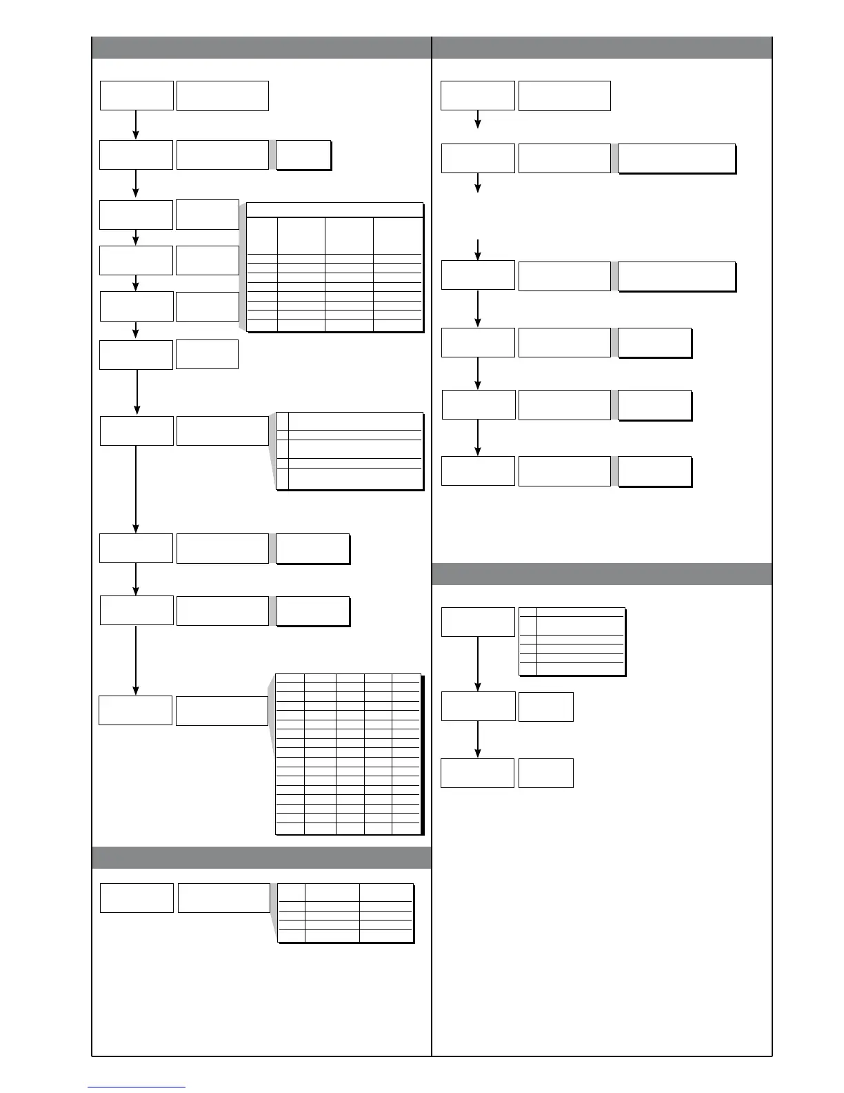
Output settings
Number of outputs 0 to 4
1. t - 2. t - 3. t - 4.t
delay for F.O. 0 to 99 min or sec
+8 to disable on power-up until first alarm
+16 to memorize
+32 to filter with F.O. mode (output filter mode)
Minimum output pulse 0 to 99 sec
Disabled by setting value 0
Displayed if associated with at least one output
Protection code
Value Displayed Modifiable
parameters parameters
0 o.1, o.2, o.3, o.4 o.1, o.2, o.3, o.4
1 o.1, o.2 o.1, o.2
2 o.1 o.1
3 o.1 none
+4 to disable In and Ou pages
+8 to disable Cf; Sr page
+16 to enable maintenance of reset latch at power-off (for linear inputs only)
+32 base configuration (the following parameters will not be displayed:
In: Ft, Fd, Of, L_L, H_L
Ou: On [forced to no. outputs present], rE)
Ft, Fd, Of remain at set value
L.L, H.L are forced to L.S, H.S
+64 Virtual instrument
+128 Disable of all the pages except P.A (Password)
Custom linearization of
main input
Step 0
(beginning of scale value)
Display limits
(-1999 to 9999 for 4 digit display)
Step 32
(end of scale value)
Display limits
(-1999 to 9999 for 4 digit display)
Step 33
mV beginning
of scale
Step 34
mV end of scale
Step 35 mV at 50°C
(*)
(*)
(*)
(*) only for tP = TC CUSTOM
U.C. Function
1 analog retransmission
output
2 Custom RTD sensor
3 Custom PTC sensor
4 Custom NTC sensor
5 Potentiometer (0 to 1V)
Output filter mode
+ 8 time base max. 99 min (default = 99 sec)
Calibration of
minimum (*)
Calibration of
maximum (*)
(*) when U.C. = 1 press keys D ∇ to calibrate
analog output
the n step value corresponds to input:
mV beginning scale + n * DmV
DmV = (mV full scale - mV beginning scale) / 32
0 not active: calculated status
is sent directly to relay
1 On delay (DON)
2 On delay after it has
been turned off (DBI)
3 Off delay (DOF)
4 Delay for activation only
at power-up (DPO)
Alarm type 1
(absolute only)
Alarm type 2
Alarm type 3
Alarm type 4
Fault action (in case of
damaged sensor)
Er, br
Value Out 1 Out 2 Out 3 Out 4
0 OFF OFF OFF OFF
1 ON OFF OFF OFF
2 OFF ON OFF OFF
3 ON ON OFF OFF
4 OFF OFF ON OFF
5 ON OFF ON OFF
6 OFF ON ON OFF
7 ON ON ON OFF
8 OFF OFF OFF ON
9 ON OFF OFF ON
10 OFF ON OFF ON
11 ON ON OFF ON
12 OFF OFF ON ON
13 ON OFF ON ON
14 OFF ON ON ON
15 ON ON ON ON
7
81641I_MHW_40T96_07-2011_ENG
 Loading...