Chapter 5 - Controls & Safety Equipment
Printed in U.S.A. 15 909793/BP0805
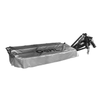
1 - Protective Cover
2 - Cover Lock Mechanism (Also see Fig. 4)
Fig. 3: Protective Cover in Operating Position
(Folded Down)
2
1
Cutterbar Protective Cover (Fig. 3)
WARNING
Be sure that the protective cover is in the op-
erating position and properly secured BE-
FORE starting the tractor engine. The cover
will stop most debris and foreign objects that
might be propelled by the rotating knives and
discs below it, but it may not stop all such ma-
terial. DO NOT operate near people. NEVER
operate the disc mower with the protective
cover in the raised position.
The protective cover (Fig. 3, Ref. 1) is designed to
contain MOST debris and foreign objects that could be
expelled by the rotating knives and discs below it. This
cover MUST ALWAYS be in the operating position
while the mower is running.
PROTECTIVE COVER LOCK
(Figs. 4 & 5)
The protective cover is provided with a lock (Fig. 4, Ref.
1) which automatically engages when the front half of
the cover is raised and folded over the rear half. This
locking feature secures the cover front half during
transport (when the cutterbar is raised into the vertical
position).
To raise the cover and place it in the transport position:
1. Insert the handle-end of the special box wrench
(Fig. 4, Ref. 3) into the access hole (Fig. 4, Ref.
2). The special box wrench is provided with the
disc mower.
2. Push to release the lock while pulling up on the
cover front half as shown.
3. Fold the cover back until it locks into the transport
position.
1 - Protective Cover Lock Mechanism
2 - Release Access Hole
3 - Special Box Wrench
Fig. 4: Releasing Protective Cover Lock
to Place Cover into Transport Position
1
2
3
 Loading...