Chapter 10 - Preparing For Field Operation
Printed in U.S.A. 31 909793/BP0805
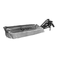
ATTACHING MOWER TO TRACTOR
1. Clean all paint from the hitch pins.
2. Refer to Fig. 24. Back the tractor to the mower and
attach the lower links to the hitch pins. Secure
links with lynch pins (Ref. 1) provided.
1 - Lynch Pins
2 - Tractor Top Link
3 - Top Link Pin
Fig. 24: Connecting Mower to Tractor
1
2
3
3. Attach the top link to the mower. Secure the link
with the pin provided. Two positions are available
to install the top link retaining pin, depending on
the diameter of the top link ball joint.
4. Connect the hydraulic lift cylinder hose to the
tractor.
5. Raise the mower with the tractor 3-point hitch
system. Fold the mower parking lock (Ref. 2) up-
ward (see arrow) until it engages in the retainer
(Ref. 1). Raise the cutterbar in and out of the trans-
port position several times to purge the air out of
the hydraulic system.
IMPORTANT: ALWAYS position the parking lock
in the upper position while transporting or
operating the disc mower.
1 - Retainer
2 - Parking Lock
Fig. 25
1
2
SETTING MOWER FRAME
WORKING HEIGHT
For Tractors Equipped with Hydraulic
Position Control of 3-Point Hitch
Refer to Fig. 26. On level ground, adjust the mower with
the tractor hydraulic 3-point lift system so that the
centers of the lower hitch pins are at a height of 15″ (420
mm) from the ground, as shown.
1 - Center of Lower Hitch Pin
2 - Adjustment Height of 15″ (420 mm)
Fig. 26
2
1
 Loading...