909793/BP0805 38 Printed in U.S.A.
CHAPTER 14
SET-UP & ASSEMBLY
UNCRATE UNIT
The DM1162 or DM1165 disc mowers are shipped from
the factory in two bundles consisting of two
main
frames and two
cutterbars. Uncrate both bundles and
divide the components into two DM1162 or DM1165
groups.
ASSEMBLY
Assemble each disc mower using the following steps:
CAUTION
The main sub-assemblies of the disc mower
are awkward and heavy and an overhead hoist
and wood blocking should be used to assist
in the safe assembly of the disc mowers.
NOTE: Some of the following steps may have
been completed at the factory
Cutterbar Installation
1. Refer to Figure 32. Clean and lubricate the bore of
the bushing (Ref. 1). Remove all protective paint
from the front cover of the gearbox (Ref. 2) where
the bushing makes contact.
1 - Bushing
2 - Gearbox
3 - Hinge Plate
Fig. 32
1
2
3
3
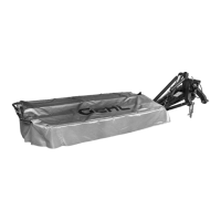
2. Refer to Fig. 33. Block the frame as necessary.
Then, attach the frame (Ref. 1) to the cutterbar
(Ref. 2) using two each self-locking cap screws
and bevel washers (Ref. 3 & 4) as shown. Tighten
the cap screws to 220 ft.-lbs. (300 Nm). If not al-
ready preassembled, use a roll pin (Ref. 6) to se-
cure the compensating spring rod (Ref. 5) to the
frame.
1 - Frame
2 - Cutterbar
3 - M16 x 50 Self-locking Cap Screw - Tighten
to 220 ft.-lbs. (300 Nm) (2 places)
Fi
. 33
1
2
3
4
3
4
4 - 16.5 mm ID x 60 mm OD Bevel Washer (2 places)
5 - Compensating Spring Rod End
6 - 8 x 50 mm Roll Pin
5
6
 Loading...