Chapter 14 - Set-up & Assembly
Printed in U.S.A. 39 909793/BP0805
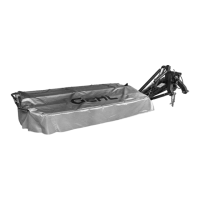
Break-away Latch Installation
3. Refer to Fig. 34. Use two pins (Ref. 4) and four roll
pins (Ref. 5) to install the break-away latch assem-
bly (Ref. 1) to the mower 3-point hitch frame (Ref.
2) and the main frame (Ref. 3).
1 - Break-away Latch
2 - Mower 3-point Hitch Frame
3 - Main Frame
4 - Pin (2 used)
5 - 6 x 36 mm Roll Pin (4 used)
Fig. 34: Break-away Latch Installation
1
2
3
4
5
5
Drive Belts and Shields Installation
4. Refer to Fig. 35. If not already preassembled, use
three spacer bolts (Ref. 3) to install the inner belt
shield (Ref. 2). Then, install the drive belts (Ref.
1). Slide the closing plate (Ref. 4) into position if
it is not already in place as shown.
1 - Drive Belts (Matched Set of 4)
2 - Inner Belt Shield
3 - Spacer Bolts (3)
4 - Closing Plate
Fig. 35: Drive Belt Installation
1
2
3
4
3
3
5. Refer to Fig. 36. To obtain the correct initial belt
tension, use the 18 mm box wrench (Ref 1. — in-
cluded with the mower) to turn the adjustment bolt
(Ref. 2) clockwise until the spacer tube (Ref. 3) is
in contact with the main frame (Ref. 4). Then, con-
tinue to turn the bolt two complete revolutions.
1 - 18 mm Box Wrench
2 - Adjustment Bolt
3 - Spacer Tube
4 - Main Frame
Fig. 36: Drive Belt Tension Adjustment
1
2
3
4
6. Refer to Fig. 37. Use (three each) washers and cap
nuts (Ref. 2) and a self-locking cap screw (Ref. 3)
to install the outer belt shield (Ref. 1).
1 - Outer Belt Shield
2 - Washers and Cap Nuts (3 each)
3 - M8 x 16 mm Self-lock Cap Screw
Fig. 37: Outer Belt Shield Installation
1
3
2
 Loading...