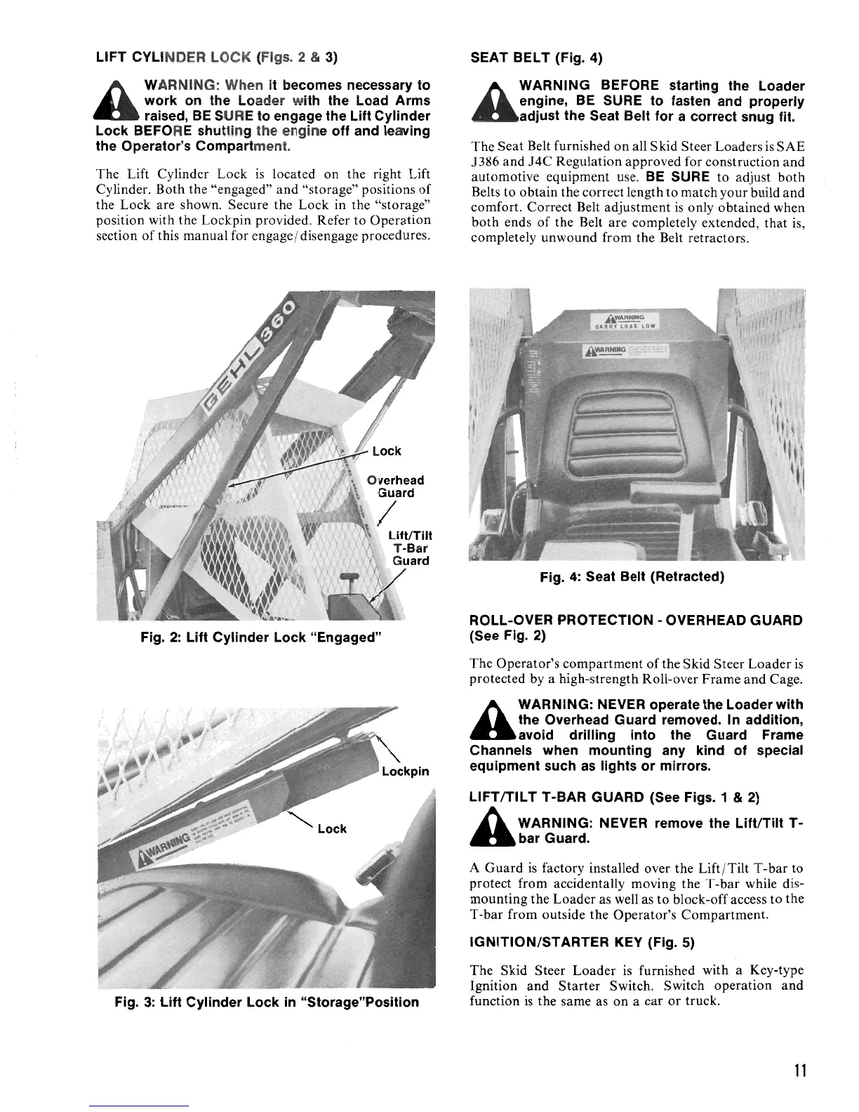
LIFT CYLI NDER LOCK (Figs. 2 & 3)
SEAT BELT (Fig. 4)
A
WARNING: When it becomes necessary to
work
on
the
Lo
ad
er w
ith
the Load Arms
raised,
BE
SURE to engage the Lift Cylinder
Lock BEFORE shutt
in
g the engine off and leaving
the Operator's Compartment.
The Lift Cylinder Lock
is
located
on
the right Lift
Cylinder. Both the "engaged"
and
"storage" positions
of
the Lock are shown. Secure the Lock in the "storage"
position with the Lockpin provided. Refer to
Operation
section
of
this manual for engage / disengage procedures.
Fig.
2:
Lift Cylinder Lock "Engaged"
A
WARNING BEFORE starting the Loader
engine,
BE
SURE
to
fasten and properly
adjust the Seat Belt for a correct snug
fit.
The
Seat Belt furnished
on
all Skid Steer Loaders
is
SAE
1386
and
J4C
Regulation approved for construction
and
automotive equipment use.
BE
SURE to adjust
both
Belts to obtain the correct length to match your build
and
comfort. Correct Belt adjustment
is
only obtained when
both
ends
of
the Belt are completely extended,
that
is,
completely unwound from the Belt retractors.
A~
CARRY tOAn
LOW
Fig.
4:
Seat Belt (Retracted)
ROLL-OVER PROTECTION - OVERHEAD GUARD
(See Fig. 2)
The Operator's
compartment
of
the Skid Steer
Loader
is
protected by a high-strength Roll-over
Frame
and
Cage.
A
WARNING: NEVER operate the Loader with
the Overhead Guard removed. In addition,
avoid drilling into the Guard Frame
Channels when mounting
any
kind
of
special
equipment such
as
lights or mirrors.
LlFTITILT T-BAR GUARD (See Figs. 1
& 2)
A WARNING: NEVER remove the Lift/Tilt
T-
"bar
Guard.
A
Guard
is
factory installed over the Lift
/Tilt
T -
bar
to
protect from accidentally moving the T-bar while dis-
mounting
the
Loader as well as
to
block-off access
to
the
T-bar
from outside the Operator's Compartment.
IGNITION/STARTER KEY (Fig. 5)
The Skid Steer
Loader
is
furnished with a Key-type
Ignition
and
Starter
Switch. Switch operation
and
function
is
the same as
on
a car or truck.
Fig.
3:
lift
Cylinder Lock
in
"Storage"Position
11
 Loading...