913218/CP0307 24 PRINTED IN U.S.A.
Middle Row Switches
Switches have graphic symbols to indicate position
and response. The following mode descriptions start
with the first switch from the left.
NOTE: Some switches are optional and may not
be on machine.
Head Lights/Work Lights: Depressing
the top of the switch will illuminate the
lights mounted on the top of the operator’s
station and the red tail lights for forward
travel operations. Depressing the bottom of
the switch will illuminate the lights at the
end of the boom in addition to the lights on the opera-
tor’s station for additional lighting in working opera-
tions.
Turn Signal: This switch is used to indi-
cate the direction of a turn with the tail
lights. Depress the right arrow for a right
turn; depress the left arrow for a left turn.
Return the switch to the center position
after the turn is completed.
Hazard: This switch can be activated to
make the tail lights flash on and off in case
the machine is stalled or temporarily
stopped in a traffic area on the road or job-
site.
Personnel Work Platform: This is a red switch used
to activate the Personnel Work Platform System. When
activated, an amber lamp in the switch will light.
NOTE: This lamp will flash on and off, indicating
that the system is not yet fully functional, until the
brakes are held on for three or more seconds.
Bottom Row Switches
Switches have graphic symbols to indicate position
and response. The following mode descriptions start
with the first switch on the left.
NOTE: Some switches are optional and may not
be on machine.
Wiper/Washer: The windshield and top
window of the operator’s station are each
equipped with a wiper and washer mecha-
nism. The left switch operates the wiper
and washer on the windshield; the second switch oper-
ates the wiper and washer on the top window.
Cold Starting: This switch activates the
injection of an ether agent for faster engine
starts in cold weather.
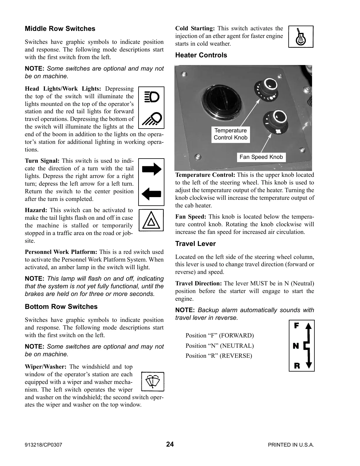
Heater Controls
Temperature Control: This is the upper knob located
to the left of the steering wheel. This knob is used to
adjust the temperature output of the heater. Turning the
knob clockwise will increase the temperature output of
the cab heater.
Fan Speed: This knob is located below the tempera-
ture control knob. Rotating the knob clockwise will
increase the fan speed for increased air circulation.
Travel Lever
Located on the left side of the steering wheel column,
this lever is used to change travel direction (forward or
reverse) and speed.
Travel Direction: The lever MUST be in N (Neutral)
position before the starter will engage to start the
engine.
NOTE: Backup alarm automatically sounds with
travel lever in reverse.
Position “F” (FORWARD)
Position “N” (NEUTRAL)
Position “R” (REVERSE)
Fan Speed Knob
Temperature
Control Knob
 Loading...