EasyManua.ls Logo

GEM WK1 - User Manual

GEM WK1
8 pages
Print Icon
To Next Page IconTo Next Page
Loading...
1
Index
Soldering point.
Male connector.
Female connector.
M/F faston connector.
Test point.
Supply voltage. Logic supply ground.
Analog supply ground.
Chassis ground.
Earth ground.
Flag joined with one or more flags
GENERALMUSIC S.p.A. Sales Division: 47842 S.Giovanni in Marignano (RN) ITALY - Via delle Rose, 12
Phone +39(0)541/959511 - Fax +39(0)541/957404 - GENERALMUSIC on the NET: http://www.generalmusic.com
Wiring Connections & Block Diagram, Power Amplifier & Supply Board Schematic Diagram.3
Opening Instructions, Video Board Installation Instructions.2
Controls Panel Board (WK1 Oriental), Video Board (Optional) Schematic Diagrams 7
Controls Panel Board (WK1), Dc/Ac Converter Board, LCD Display Board, Volume Board,
5 Cpu & Sound Generator Board (WK1 & WK1 Oriental) Schematic Diagram
6
Modulation Board, Keyboard L/R Contact Board Schematic Diagrams
8
Spare Part List
Timing Table
4
SERVICE MANUAL
CODE: 270275
Warnings
with the same signal name inscribed.
Address
ATTENTION
Observe
precautions when handling electrostatic sensitive devices.
Notice
Service must be carried out by qualified personnel only. Any tampering carried out by unqualified personnel during the guarantee period
will forfeit the right to guarantee.
For a correct operation of the instrument, after having switched off, be careful to wait at least 3 seconds before switching on again.
To improve the device's specifications, the schematic diagrams may be subject to change without prior notice.
All components marked by this symbol have special safety characteristics, when replacing any of these components use only
manufacturer's specified parts.
The (µ) micro symbol of capacitance value is substituted by U.
The (
) omega symbol of resistance value is substituted by E.
The electrolytic capacitors are 25Vdc rated voltage unless otherwise specified.
All resistors are 1/8W unless otherwise specified.
All switches shown in the "OFF" position. All DC voltages measured to ground with a voltmeter 20KOhm/V.
Question and Answer IconNeed help?

Do you have a question about the GEM WK1 and is the answer not in the manual?

Summary

Warnings and Safety Information

Service Notice

Safety instructions for qualified personnel and device operation precautions.

Electrostatic Discharge Precautions

Guidelines for handling sensitive electronic components.

System Architecture and Schematics

Power Amplifier & Supply Board Schematic

Detailed circuit diagram for power and audio amplification stages.

Board Level Schematics

Controls Panel and Keyboard Contact Board Schematics

Circuit diagrams for user controls and keyboard input contacts.

CPU, Sound, and Video Schematics

CPU & Sound Generator Board Schematics

Circuit diagrams for the main processor and sound generation.

WK1 Oriental Controls and Optional Video Board

WK1 Oriental Controls Panel Schematic

Detailed circuit diagram for the WK1 Oriental control panel.

Overview

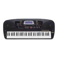
This document serves as a comprehensive service manual for the GEM WK1 and WK1 Oriental World Keyboard instruments, providing detailed instructions for maintenance, repair, and understanding of its internal architecture.

Function Description:

The GEM WK1 and WK1 Oriental are electronic keyboards designed for musical performance. They incorporate a range of features including sound generation, MIDI capabilities, a floppy disk drive for data storage and retrieval, and an optional video output for display on an external monitor. The instrument's core functions are managed by a CPU and sound generator board, which processes user input from the keyboard and control panel to produce various musical sounds and effects. The modular design, as indicated by the block diagram, allows for distinct sections such as power amplification, display, modulation, and keyboard contact scanning to operate cohesively.

Important Technical Specifications:

  • Power Supply: The instrument operates with an AC/DC adapter, converting mains power to the necessary DC voltages for internal components. It also features a 12V NiCd battery for data backup, ensuring settings and data are retained for up to 30 days during power off.
  • Audio Output: The power amplifier and supply board (731048) drives the audio output, with separate sections for left and right channels, and includes a headphone output. Output levels are specified, for instance, 5.5±0.5Vpp from PHONES 2 and 0.8Vpp ±5% from AUX OUTPUTS.
  • Video Output (Optional): The optional video board (761232) supports both PAL (Europe) and NTSC (USA) video standards, providing RGB and S-VHS output. Key video timings include VSYNC at 20ms/50Hz and HSYNC at 64us/15.625Hz.
  • MIDI Connectivity: The instrument supports MIDI IN and OUT, allowing it to interface with other MIDI-compatible devices and computers.
  • CPU & Sound Generator: The CPU & Sound Generator Board (761233 for WK1, 761242 for WK1 Oriental) is the central processing unit, responsible for managing all instrument functions, sound synthesis, and data processing.
  • Keyboard: The keyboard features 61 notes, with separate contact boards for left (31 notes) and right (30 notes) sections, ensuring precise detection of key presses and dynamic response.
  • Display: An LCD display board (MDL735020) provides visual feedback for settings, song names, and other operational information.
  • Floppy Disk Drive: A 3.5" diskette drive is integrated for loading and saving MIDI files and operating system updates.
  • Control Panel: The control panel (MDL815011 for WK1, MDL815012 for WK1 Oriental) features numerous push buttons and LEDs for intuitive control over the instrument's functions.
  • DA Converter: The DA Converter (PCM69AU) handles digital-to-analog conversion for audio signals, with specified timings for SL, SDO/SD1, and SCK signals.

Usage Features:

  • Operating System (OS) Management: The instrument allows for OS updates via the floppy disk drive, ensuring access to the latest features and bug fixes. A system reset function restores the initial manufacturer memory configuration.
  • Dynamic Keyboard Response: The keyboard is designed for uniform dynamic response across all keys, which can be checked during the test procedure.
  • Pedal Support: It supports both volume pedals and switch pedals (damper), with automatic recognition of pedal type (normally closed or normally open) upon system reset or power-on.
  • MIDI Local On/Off: The MIDI functionality includes a "local off" mode, allowing the keyboard to send events through an external MIDI loop without triggering internal sound generation, useful for studio setups.
  • Computer Interface: The instrument can be configured to link with a PC (PC1 or PC2 settings) for data exchange.
  • Sound ROM Test: A procedure is outlined to test various sounds and styles from the instrument's internal ROM, ensuring proper sound generation across different patches and drum styles.

Maintenance Features:

  • Modular Design: The instrument's internal structure is highly modular, with separate boards for different functionalities (e.g., CPU, power supply, display, keyboard contacts). This simplifies troubleshooting and component replacement.
  • Test Procedure: A detailed test procedure is provided to verify proper instrument operation after repairs. This includes checks for the operating system, video output, keyboard, control panel, RAM backup, headphones, pedals, MIDI, computer interface, floppy disk drive, and sound ROM.
  • Component Replacement: The manual emphasizes using manufacturer-specified parts for components marked with a special safety symbol, ensuring continued safety and performance.
  • Electrostatic Sensitive Devices (ESD) Handling: A warning is included to observe precautions when handling ESDs, crucial for protecting sensitive electronic components during service.
  • Reliability Check: Before reassembly and delivery, a reliability check is recommended, involving careful shaking of boards and connections with an insulated tool to identify any loose or faulty contacts.
  • Capacitor Specifications: Electrolytic capacitors are generally rated at 25Vdc unless otherwise specified, and resistors are 1/8W.
  • Voltage Measurement: All DC voltages are to be measured to ground with a voltmeter at 20KOhm/V.
  • Timings Table: Detailed timing diagrams are provided for power on/off, LED bar, keyboard and control panel, DA converter, and video interface, which are essential for diagnosing timing-related issues.
  • Spare Part List: A comprehensive spare part list is included, categorizing parts by function (e.g., CPU & Sound Generator, Power Amplifier & Supply, Keyboard Assembly) and providing part numbers for easy identification and ordering. This list also includes accessories and cabinet assembly parts.

GEM WK1 Specifications

General IconGeneral
BrandGEM
ModelWK1
CategoryKeyboard
LanguageEnglish