<4>
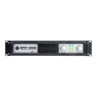
GPA SERIES POWER AMPLIFIERS
INTRODUCTION:
Congratulations on purchasing a G
EMINI GPA SERIES POWER AMPLIFIER.
This state of-the-art power amplifier includes the latest features & is backed
by a THREE year limited warranty. Prior to use, we suggest that you careful-
ly read all the instructions.
FEATURES:
- 30 Hz to 50 kHz frequency response, <0.05% THD (0.02% typical)
- High output power to drive professional loudspeakers without clipping
- Comprehensive protection circuitry with protect LED indicator
- ¼" TRS & XLR balanced/unbalanced inputs
- Speakon & ¼" speaker outputs
- Three modes of operation - stereo, parallel mono, and mono bridge
- Ground lift switch
- Decibel (dB) level meter with clip LEDs
- Subsonic and ultrasonic filters for better protection and more efficient
operation
- Aluminum extrusion heat sink design with directly mounted output tran-
sistors for no-fault operation
- Air guide with front-to-rear airflow and cooling fan for thermal stability
and reliability
CAUTIONS:
1. Read all operating instructions before using this equipment.
2. To reduce the risk of electrical shock, do not open the unit. There are
N
O USER REPLACEABLE PARTS INSIDE. Please contact the GEMINI SERVICE
D
EPARTMENT
or your authorized dealer to speak to a qualified G
EMINI SOUND
PRODUCTS technician.
3. In the USA: If you experience problems with this unit, please visit
HTTP://WWW.GEMINIDJ.COM/SUPPORT.HTML or call 1 (732) 738-9003 for GEMINI
CUSTOMER
SERVICE
. Do not attempt to return this equipment to your deal-
er.
4. Be sure to allow adequate front & rear ventilation to avoid possible heat
damage to your equipment.
5. Be sure that the power is O
FF before making connections. This will elim-
inate any chance of unexpected, loud audio transients that could damage
your speakers or amplifier.
6. Be sure that the power is O
FF when changing modes of operation &
when changing the position of the Ground Lift Switch.
7. D
O NOT EXPOSE THIS UNIT TO RAIN OR MOISTURE. Operators of electron-
ic equipment should in no way be in contact with water.
8.
NEVER DEFEAT THE GROUND PIN OR POLARIZED BLADES found on the 3-
prong power plug. Defeating this safety feature poses a risk of electrocu-
tion. If your outlets do not comply to these standards, contact an electri-
cian.
9. D
O NOT USE ANY SPRAY CLEANER OR LUBRICANT ON ANY CONTROLS OR
SWITCHES.
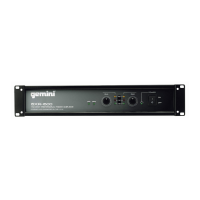
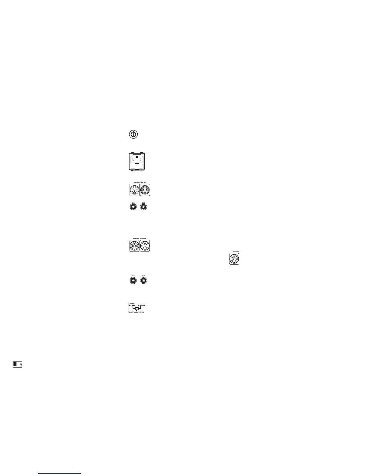
CONNECTIONS:
1. Before plugging this unit into any outlet, make sure that the
VOLTAGE SELECTOR (1) switch is set to the proper voltage. To change the
selection, unscrew the hard plastic protective top with a Phillips head
screw driver. Then use a flat head screw driver to move the switch to the
proper selection (115 V/230 V).
2. Ensure that the P
OWER BUTTON (11) is in the OFF position prior to
making any connections. This unit comes with a POWER CORD (2).
Plug into the rear panel AC IN WITH FUSE (3) jack before plugging it
into a proper power source.
NOTE:
LOCATED BY THE AC IN WITH FUSE
(3) IS A 250 V FUSE TO
PROTECT AGAINST ELECTRICAL SURGES. TO REPLACE THE FUSE
, FIRST
DISCONNECT THE
P
OWER CORD
(2), AND PLACE A FLAT HEAD SCREW
-
DRIVER INTO THE GROOVE LOCATED INSIDE THE AC IN WITH FUSE (3)
&
DISLODGE THE FUSE
. REPLACE THE FUSE WITH ONLY A
250 V FUSE.
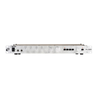
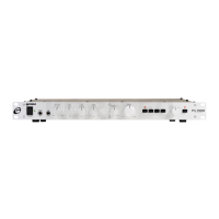
3. The GPA series has 2 sets of inputs:
- The XLR B
ALANCED I
NPUTS
(10) accept a line level signal.
With standard three prong XLR connections, prong 1 is the
ground, prong 2 is hot or positive (+) & prong 3 is cold or
negative (-).
- The ¼" TRS B
ALANCED INPUTS (9) accept a balanced as well
as an unbalanced line level signal. The unbalanced line uses a
standard tip-sleeve connection. The tip is positive & the sleeve is negative
or ground. The balanced line uses a tip-ring-sleeve connection. (TRS) The tip is hot
or positive (+), the ring is cold or negative (-), & the sleeve is shield or
ground.
4. The GPA series has 2 sets of outputs.
- The 2 S
PEAKON OUTPUTS (4) connect speakers to the
amplifier.
- The B
RIDGE OUTPUT SPEAKON (5) connects the
speakers to the amplifier only in M
ONO BRIDGED
OPERATION. This
mode allows the entire power of the amplifier to be used with one
mono channel. This mode of output is meant only for 8 ohms or
greater impedance.
- The ¼" S
PEAKER OUTPUTS (6) connect speakers to the
amplifier.
NOTE: M
AKE SURE THE POWER BUTTON (11) IS IN THE OFF POSITION BEFORE
MAKING ANY CONNECTIONS
.
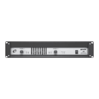
OPERATIONS:
1. O
PERATION MODE SWITCH: The OPERATION MODE SWITCH (8) is
used to set the unit for STEREO mode, PARALLEL MONO mode or
MONO BRIDGE mode. Total speaker impedance must not be
lower than 4 Ohms per channel for S
TEREO & PARALLEL MONO modes, & 8
Ohm for MONO BRIDGE mode.
NOTE:
THE AMPLIFIER'S POWER BUTTON (11) MUST BE TURNED OFF WHEN CHANG-
ING MODES OF OPERATION.
- S
TEREO OPERATION: The unit has two channels for STEREO operation. Each
channel provides a separate & discrete signal at the speaker outputs
according to the signal received at the inputs. The following instructions
are for applications with 4 Ohm to 8 Ohm speakers of matched power rat-
ings.
With the power OFF, set the OPERATION MODE SWITCH (8) to the STEREO
position.
With the power O
FF, connect your input cables to the CH 1 & CH 2 inputs
using the XLR BALANCED INPUTS (10) or ¼" TRS BALANCED INPUTS (9) of
each channel.
Connect the loudspeakers to either the CH 1 & CH 2 S
PEAKON (4) or
¼"SPEAKER
OUTPUTS
(6).
NOTE:
THE TOTAL SPEAKER LOAD MUST BE AT LEAST
4 OHMS PER CHANNEL
. IF YOU
TRY TO OPERATE AT A LOWER IMPEDANCE
, THE AMPLIFIER WILL GO INTO PROTECTION
MODE
& CEASE OPERATING UNTIL YOU CORRECT THE LOAD CONDITIONS.
With the CH 1 (13) & CH 2 (14) volume rotary controls set to zero (fully
counterclockwise), push the P
OWER BUTTON (11) to turn ON the amplifier.
Apply a signal to the input of the amplifier. The level of the input signal
should be as high as you will ever need it to be. This way, it will be as high
above the amplifier's noise floor as possible, ensuring an excellent per-
formance & signal to noise ratio. Adjust the CH 1 (13) & CH 2 (14) volume
rotary controls for each channel to achieve the desired maximum listening
level, or the maximum output level of the speaker systems, whichever comes first.
NOTE:
WHEN THE CLIP LEDS LIGHT, THERE IS DISTORTION PRESENT IN THE AMPLI-
FIER'S OUTPUT SECTION. IF A CLIP LED LOCATED AT THE TOP OF THE VU METER (15)
REMAINS ON OR FLASHES REPEATEDLY, REDUCE THE SIGNAL LEVEL BY LOWERING THE
INPUT LEVEL CONTROL FOR THE CHANNEL THAT IS CLIPPING OR REDUCE THE LEVEL
AT THE SOURCE
.
- P
ARALLEL MONO OPERATION: When the amplifier is in PARALLEL MONO
mode, the same monophonic signal is output on both output channels of
the S
PEAKON
OUTPUTS
(4) & ¼” SPEAKER
OUTPUTS
(6). Each channel's output
is controlled independently by the respective CH 1 (13) & CH 2 (14) vol-
ume rotary controls.
With the power O
FF, set the OPERATION MODE SWITCH (8) to the PARALLEL
MONO position.
With the power O
FF
, connect your input cable to the CH 1 input only
using the XLR BALANCED INPUT (10) or ¼" TRS BALANCED INPUT (9) of chan-
nel 1.
Connect the loudspeakers to both S
PEAKON OUTPUTS (4) or ¼" OUTPUTS
(6).
NOTE:
THE TOTAL SPEAKER LOAD MUST BE AT LEAST 4 OHMS PER CHANNEL. IF YOU
TRY TO OPERATE AT A LOWER IMPEDANCE
, THE AMPLIFIER WILL GO INTO PROTECTION
MODE & STOP OPERATION UNTIL YOU CORRECT THE LOAD CONDITIONS.
With the CH 1 (13) & CH 2 (14) volume rotary controls set to zero (fully
counterclockwise), push the P
OWER BUTTON (11) to turn ON the amplifier.
Apply a signal to the input. The level of the input signal should be as high
as you will ever need it to be. This way, it will be as high above the ampli-
fier's noise floor as possible, ensuring an excellent performance & signal to
noise ratio. Adjust the CH 1 (13) & CH 2 (14) volume rotary controls to
achieve the desired maximum listening level.
NOTE:
WHEN THE CLIP LEDS LIGHT, THERE IS DISTORTION PRESENT IN THE AMPLI-
FIER
'S OUTPUT SECTION. IF A CLIP LED REMAINS ON OR FLASHES REPEATEDLY,
REDUCE THE SIGNAL LEVEL BY LOWERING THE INPUT LEVEL CONTROL FOR THE CHAN-
NEL THAT IS CLIPPING OR REDUCE THE LEVEL AT THE SOURCE.
- MONO BRIDGE OPERATION: Bridging the amplifier converts the unit to a
 Loading...