PG 8
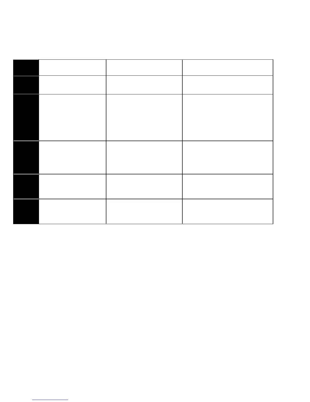
The Wire Chart below will help you determine the terminal connections you will use
on your new thermostat. See chart section that applies to your heat/cool system.
OLD THERMOSTAT NEW THERMOSTAT DESCRIPTION
R or RH or 4 or V RH or RC(leave jumper) Power Wire
RH or 4 or V RH (remove jumper) Power Heat
RC or R RC (remove jumper) Power cool
W or H W Heat return
Y or M Y Cool return (compressor)
G or F G Fan return
C or X C AC source for thermostat
W2 or H2 W2 2nd stage of heat
Y2 do not connect 2nd stage of cool (n/a)
W2 W2 Heat pump Aux heat
E Do not connect
O (see note below) O Dmpr/Chg-over (pwr in cool)
B (see note below) B Dmpr/Chg-over (pwr in heat)
5 or R RH Power wire (pwr)
4 or W W Turn Valve on
6 or Y or B A Turn Valve off
R RH Power wire (pwr)
Y or B W Turn Valve off
W A Turn Valve on
ONE
Power
Wire
TWO
Power
Wires
ZONED
MOTOR
VALVES
ZONED
SOLENOID
VALVES
HEAT
PUMPS
Note: On a heat pump, if O and B are both present, connect O to O and tape off B.
For wiring support visit our website at www.Gemtech-thermostats.com
Control wires
 Loading...