Choosing and installing
the loudspeaker cables
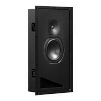
The RAM1 amplifier unit has separate
power ampliers for the tweeter and woofer.
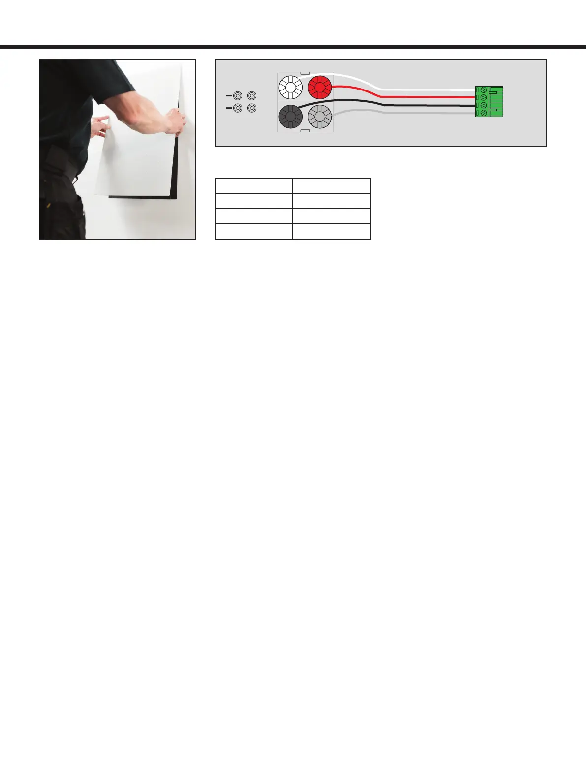
Accordingly, there are two pairs of binding
posts, white (-) and red (+) for the tweeter and
black (-) and grey (+) for the woofer. At the
loudspeaker end, the cables are connected
to a screw block terminal, which plugs into
the input connector on the loudspeaker
enclosure. Be sure to maintain correct
polarity when connecting the loudspeaker
cables and be extra careful not to mix the
tweeter and woofer cables (See Figure 7).
Use a good quality 4-conductor cable and
make the cable runs as short as possible.
See Table 1 for recommended cable gauges.
The terminals accept a cable up to 6 mm
2
(9 gauge).
If you are installing the AIW26B system
to an existing wall, examine the walls
thoroughly for the shortest and least
obstructed cable route. Be careful to avoid
cutting or drilling into electrical wires,
ventilation or water pipes. These are often
visible in the attic, basement or crawl space
below the oor. It is a good idea to route the
loudspeaker cables away from electric or
video cables, which might induce hum into
the loudspeaker system.
Connecting the RAM1
amplifier
The RAM1 amplifier is designed to be
connected to a line level output of a
preamplifier, Surround Sound processor
or other low level source. NOTE! Never
connect the RAM1 to a loudspeaker level
output of a power amplier! Before making
the connections, check that the voltage
selector on the amplier’s back panel is set
to the correct voltage and the power on all
components is turned o.
Start by connecting the loudspeaker
cables to the amplier’s binding posts (see
Fig. 7 and 9). Check that the amplifier’s
serial number matches that of the AIW26B
loudspeaker enclosure which it will power.
The number can be found on a sticker on
the loudspeaker’s reflex port and on the
amplifier’s top cover. If the loudspeakers
are not yet installed, make a note of
which amplifier is connected to each
channel. Check the cable polarity and use
the provided cable binding post tool to
tighten the binding posts. Be careful not to
overtighten the binding posts as they may
be damaged.
The RAM1 has two parallel 10 kOhm
input connectors: a balanced XLR and
an unbalanced RCA. For longer cable
connection lengths (>10m or >30ft) a
balanced line connection is recommended
as it offers better immunity to external
interference. The RCA connection
method usually works as well for shorter
connection lengths in less electrically noisy
environments. Do not use both inputs at the
same time. Consult your Genelec dealer for
the choice of signal cables.
The RAM1 has a provision for remote
controlled switching between “ON” and
“STANDBY” modes (not available in units
sold in the EU). The “REMOTE CONTROL”
connector block has two connector pairs:
1-2 for a 12 V DC trigger remote control
and 3-4 for an external switch or relay type
(contact closure) remote control (see Table
2). Do not connect two remote controls to
the amplier at the same time.
Space requirement for the
RAM1 amplifier
The dual 120 W power ampliers of a RAM1
unit generate a large amount of heat when
used at full power. To avoid overheating,
ensure that there is good airow around the
amplier and no external heat sources close
to it. We recommend installing the RAM1
into a well ventilated equipment rack using
its dedicated RM1 4U rack mount kit.
If the RAM1 amplifier is placed in a
cabinet, on a shelf or into an equipment rack
without its dedicated RM1 rack mount kit,
there must be at least 100 mm (4 in) of free
space behind, 150 mm (6 in) above and 50
mm (2 in) on both sides of the amplier to
ensure adequate cooling (see gure 10).
Mounting the RAM1 amplifier
to an equipment rack
We recommend that you use the Genelec
RM1 4U rack mount kit when installing the
RAM1 amplier in an equipment rack. Make
sure that the space above and below the
RAM1 is uncluttered and there is a space of
100 mm (4 in) or more behind the amplier.
The space behind the amplifier must be
well ventilated. If the temperature inside
the rack is likely to rise close to the RAM1’s
maximum ambient temperature of 35° C
(95° F), we recommend installing ventilation
fans to ensure that the thermal protection
is not activated prematurely. See gure 11.
Setting the input sensitivity
The input sensitivity of each amplier can
be made to match that of the decoder or
other source by use of the input sensitivity
control on the amplier’s front panel (see
+
WOOFER
+
TWEETER
WOOFER
TWEETER
-
+
-
+
TWEETER
WOOFER
Figure 6. The metal mesh grille is held in
place by magnets.
Figure 7. Correct loudspeaker cable polarity.
Cable gauge Max. length
2,0 mm
2
(14 AWG) 30 m (100 ft)
3,3 mm
2
(12 AWG) 40 m (130 ft)
5,3 mm
2
(10 AWG) 60 m (200 ft)
Table 1. Recommended cable thicknesses
for dierent lengths of loudspeaker cable.
 Loading...