Do you have a question about the Generac Power Systems 004992-0, 004992-1, 37kW NG, 40kW LP and is the answer not in the manual?
| Model Number | 004992-0, 004992-1 |
|---|---|
| Power Output (NG) | 37 kW |
| Power Output (LP) | 40 kW |
| Voltage | 120/240 V |
| Frequency | 60 Hz |
| Fuel Type | Natural Gas (NG), Liquid Propane (LP) |
| Sound Level | 67 dBA at 23 ft (7 m) |
| Dimensions (L x W x H) | 48 x 25 x 29 inches |
| Phase | 1-Phase |
Welcome and thank you for purchasing this Guardian standby generator product line.
Key safety guidelines for operating and maintaining the generator, to be posted in hazard areas.
Overview of general safety risks associated with the generator, installation, and operation.
Details specific risks and precautions related to electrical shock and safe handling practices.
Information on fire risks and preventative measures, including extinguisher use.
Guidance on preventing explosive gas buildup and related risks from fuel.
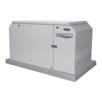
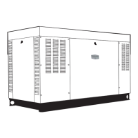
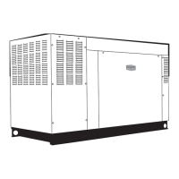
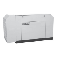
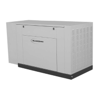
Description of the liquid-cooled, engine-driven generator set and its purpose.
Information on the matched 200 amp automatic transfer switch and its installation requirements.
Explanation of how the generator and transfer switch work together for automatic power supply.
Details on the single-phase, three-wire generator AC connection system.
Information about the generator's main circuit breaker as shipped from the factory.
Specifications and considerations for natural gas and LP vapor fuel systems.
Overview of safety switches that automatically shut down the engine under fault conditions.
Details on the low oil pressure safety switch function and its effect.
Explanation of the high coolant temperature safety switch and its activation.
Information on the low coolant level sensor and its function to prevent overheating.
How the engine overspeed shutdown mechanism operates based on AC frequency.
Function of the RPM sensor loss shutdown feature and its indicator.
Details on the engine's overcrank shutdown sequence after multiple failed start attempts.
Explanation of the low battery alarm and its effect on starting and operation.
Procedure for resetting engine alarms and restarting the unit using the AUTO/OFF/MANUAL switch.
Location and function of DC fuses protecting the control console wiring and components.
Instructions and precautions for unpacking the generator set to avoid damage.
Safety warnings and considerations for lifting the generator due to its weight.
Technical specifications for both the generator and engine.
Fuel consumption rates for natural gas and LP vapor at various load percentages.
Steps to convert the generator's fuel system from natural gas to LP vapor.
Specified torque values for various engine bolts like cylinder head and manifold.
Recommended engine oil types and viscosity based on ambient temperature.
Guidelines for engine coolant mixture, capacity, and types of antifreeze.
Pre-installation checks for generator and transfer switch ratings and load capacity.
General requirements and safety precautions for standby generator installation.
List of relevant NFPA standards for standby electric systems installation.
List of other relevant standards and codes for installation.
Guidelines for selecting an appropriate location for the generator set.
Instructions for mounting and supporting the generator securely.
Schematic and explanation of a basic standby electric system setup.
Method to prevent generator overloading by isolating critical loads.
Method for powering all electrical loads, potential for generator overload.
Procedures and safety precautions for grounding the generator frame.
Information on Generac's ungrounded AC neutral and connection requirements.
How to connect control wires for pre-packaged and GTS-type transfer switches.
Safety precautions and instructions for installing the generator's battery.
Procedures to follow before the initial start-up of the generator.
Important pre-start checks for fluids and preparation.
Requirements for installing a transfer switch as per the National Electrical Code.
Checks for correct fuel supply pressure, purging, and leak testing.
Checking engine oil level before operation and adding oil if needed.
Procedures for filling the engine cooling system with the recommended coolant.
Checking engine fan belt tension and condition before service.
Ensuring the generator is properly connected to an earth ground.
How to use the generator with a Generac "GTS" type automatic transfer switch.
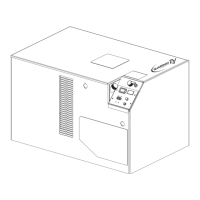
Identification and function of components on the generator's control console.
Operation of the three-position AUTO/OFF/MANUAL switch.
Explanation of fault indicator LEDs and the conditions they represent.
Function of the 15 Amp fuse protecting the DC control circuit.
Function of the 4.0 Amp fuse protecting the battery charger.
How to program the generator for automatic starting and exercising.
Purpose and indication of the System Ready LED on the control panel.
Steps for manually transferring electrical loads and starting the engine.
Procedure for adjusting engine speed governor settings if necessary.
Steps for transferring loads back to utility power and shutting down the generator.
Instructions for setting the system to operate fully automatically.
How to set and perform the weekly generator exercise cycle.
Recommended maintenance tasks to be performed by authorized service dealers.
Importance of keeping air intake and outlet openings clear for proper cooling.
Explanation of how overcurrent protection devices prevent electrical system overload.
Procedures for checking essential fluid levels like engine oil, battery fluid, and coolant.
Steps for checking engine oil level using the dipstick.
Weekly checks for battery electrolyte fluid level and adding distilled water.
Checking the engine coolant level in the recovery bottle.
Routine maintenance tasks that the owner or operator can perform.
Refer to "Checking Fluid Levels" in Section 4.4 for oil checks.
Checking battery fluid level, cables for condition, tightness, and corrosion.
Instructions for manually starting and running the generator weekly if not automated.
Monthly inspection of cooling system hoses, clamps, and for leaks.
Refer to "Checking Fluid Levels" in Section 4.4 for coolant checks.
Monthly visual inspection for damage, leaks, loose fasteners, or corrosion.
Three-month inspection of exhaust system pipes, mufflers, clamps, etc.
Three-month inspection of fan belts for damage and checking belt tension.
Visual inspection of the electronic governor; adjustment by qualified personnel only.
Procedure for draining warm engine oil and replacing the oil filter.
Steps for replacing the engine air filter.
Instructions for cleaning, checking, and adjusting spark plug gaps.
Annual coolant system drain, flush, and refill by an authorized dealer.
General maintenance tasks for the generator's cleanliness and upkeep.
Keeping the generator clean and dry to maintain insulation resistance.
Precautions for handling batteries and avoiding hazards like explosion or chemical burns.
Inspection of battery posts, cables, and fluid levels.
Information on the correct battery type and number for replacement.
Engine wiring diagram showing connections and components.
Exploded view and parts list for the generator's mounting base.
Exploded view and parts list for the generator enclosure components.
Exploded view and parts list for the generator's control panel assembly.
Exploded view and parts list for the engine components.
Exploded view and parts list for the generator's radiator assembly.
Exploded view and parts list for the generator's fuel system components.
Exploded view and parts list for the generator's alternator assembly.