Do you have a question about the Generac Power Systems QuietSource 005028-0 and is the answer not in the manual?
Essential safety guidelines for operating and maintaining the generator.
Information on general safety precautions and potential hazards associated with the equipment.
Details on the risks of electrical shock and safe handling procedures.
Precautions regarding flammable fuels and potential fire or explosion risks.
References to relevant codes and standards for installation guidance.
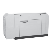
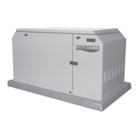
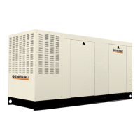
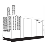
Description of the liquid-cooled standby generator and its capabilities.
Information on transfer switches used with the generator system.
Explanation of how the generator operates with an ATS.
Details on the generator's operation with an engineered transfer switch.
Description of the generator's AC output connection configuration.
Information on the generator's fuel system and fuel pressure requirements.
Details on safety switches that shut down the engine automatically.
Technical specifications for the engine and generator components.
Data on fuel usage for natural gas and LP gas.
Instructions for converting the fuel system from natural gas to LP vapor.
Guidance on selecting the appropriate engine oil and viscosity.
Information on the recommended coolant mixture and system capacity.
Key checks and considerations before proceeding with installation.
Procedures and safety requirements for installing the standby generator.
Guidelines for selecting an appropriate location and mounting the generator.
Schematic and explanation of a typical standby generator setup.
Methods for isolating circuits and grounding the generator properly.
Details on connecting and operating the generator with an ATS.
Instructions and safety precautions for installing the generator battery.
Essential steps to perform before the initial start-up of the generator.
Specific checks required before the first engine start.
Identification and function of the generator's control console elements.
Procedure for manually transferring loads and starting the generator.
Information on adjusting engine governor gain settings.
Steps for transferring loads back to utility and shutting down the generator.
Setting up automatic operation and scheduling weekly exercise cycles.
Configuration options for the generator control board via DIP switches.
Procedure for adjusting the voltage regulator settings.
List of maintenance tasks performed by qualified service technicians.
Instructions for servicing the exhaust manifold.
Instructions for servicing the intake manifold.
Procedure for cylinder head maintenance.
Information on inspecting and maintaining the engine's cooling system.
Details on DC electrical system overload protection.
Procedures for checking engine oil and coolant levels.
Maintenance tasks that can be performed by the owner or operator.
Procedure for changing the engine oil and filter.
Instructions for replacing the air cleaner and servicing spark plugs.
Recommendations for changing the engine coolant annually.
Guidelines for cleaning the generator's exterior and interior.
Procedures for inspecting and maintaining the generator battery.
Common problems and their causes and corrections.
Electrical wiring diagram for 15kW and 20kW units.
Key for symbols and components used in the control panel.
Legend for customer connection and alternator wiring.
Legend for engine wiring connections.
Electrical schematic for the 25kW unit.
Exploded view and parts list for the generator mounting base.
Exploded view and parts list for the generator enclosure.
Exploded view and parts list for the generator control panel.
Exploded view and parts list for the generator engine.
Exploded view and parts list for the generator fuel system.
Exploded view and parts list for the generator alternator.
Exploded view and parts list for the generator muffler.
Exploded view and parts list for the stepper motor.
Exploded view and parts list for the generator radiator.
Diagram showing the overall installation layout and dimensions.
Statement of warranty rights and obligations for emission control systems.
Owner's responsibilities regarding maintenance and warranty claims.
Details on the coverage and period of the ECS warranty.
Overview of the two-year limited warranty for the generator.
Schedule outlining warranty coverage for labor and parts.
List of conditions and situations not covered by the warranty.
| Model Number | 005028-0 |
|---|---|
| Category | Inverter |
| Brand | Generac Power Systems |
| Series | QuietSource |
| Frequency | 60 Hz |
| Voltage | 120/240 VAC |
| Rated Wattage | 5000 W |
| Phase | Single Phase |