Do you have a question about the Generac Power Systems Guardian 005260-1 and is the answer not in the manual?
General safety precautions and warnings for operation, installation, and service.
Warnings about dangerous voltages, shock hazards, and proper electrical safety practices.
Precautions related to fire risks, including extinguisher use and keeping area clear.
Safety measures to prevent explosions, focusing on ventilation and fuel handling.
Emphasizes the importance of reading and understanding the manual before operation.
Outlines the operator's responsibility for safety checks and prompt maintenance.
Provides guidance on contacting authorized dealers for service and repair needs.
Details about the generator's data label, serial number, and model identification.
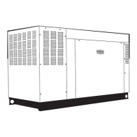
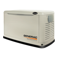
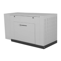
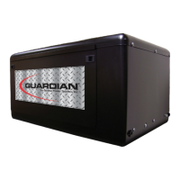
Overview of the generator set's components, features, and construction.
Specific guidance on engine oil type and viscosity based on ambient temperature.
Recommendations for coolant mixture, type, and handling of the cooling system.
Describes the function of the high coolant temperature switch for engine shutdown.
Explains the low coolant level sensor's role in preventing engine overheat shutdown.
Details the low oil pressure switch that shuts down the engine if oil pressure drops.
Explains the function of the overcrank shutdown to prevent starter damage.
Describes the overspeed shutdown feature to protect the engine from excessive RPM.
Explains the shutdown triggered by a loss of engine speed signal.
Information about the DC fuse protecting the control panel from overload.
Specifies the required fuel pressure and Btu content for natural gas and LP gas.
Information on natural gas supply, pressure regulation, and system requirements.
Details on propane vapor systems, their suitability, and ambient temperature effects.
Explanation of LP fuel systems, vaporization, and conversion to gaseous state.
Technical specifications for the generator, including insulation, distortion, and lead connections.
Specifications for the cooling system, such as water pump, fan, and coolant capacity.
Specifications for fuel system components like type, regulator, and operating pressure.
Engine specifications, including make, model, displacement, bore, stroke, and parameters.
Specifications for the electrical system, including battery, voltage regulator, and ambient conditions.
Steps and checks required before initial start-up, including safety and fluid levels.
Requirements for transfer switch installation to prevent backfeed and ensure code compliance.
Checks for correct fuel supply, pressure, purging, and leak testing.
Instructions for checking and maintaining engine oil and gearbox oil levels.
Critical pre-start preparation steps, including fluid checks and warnings.
A checklist of initial inspections before starting the generator set.
Detailed steps for preparing the unit before the initial start-up sequence.
Information regarding the formal start-up inspection form and its distribution.
Guidance on controlling and operating the generator set via the control panel.
Procedures for operating the generator with a manual transfer switch.
Steps for starting the engine and transferring the load manually.
Procedures for transferring load back to utility and shutting down the generator.
Notes on operating the generator with an automatic transfer switch.
Tasks requiring professional service, categorized by intervals (3 months, 6 months, annually).
Maintenance requirements for the cooling system, including air flow and obstructions.
Information on circuit breakers and fuses protecting the DC electrical system.
Procedures for checking engine oil level, battery fluid, and engine coolant.
Detailed steps for checking the engine oil level using the dipstick.
Reference to checking fluid levels for engine oil.
Instructions for checking battery condition, cables, and charging.
Recommendation to start and run the generator regularly for system exercise.
Guidance on inspecting the cooling system for hoses, clamps, and leaks.
Reference to checking fluid levels for engine coolant.
General visual inspection of the engine-generator for damage and leaks.
Periodic inspection of the exhaust system components for condition and leaks.
Inspection of fan belts for wear, damage, and proper tension.
Visual inspection of the electronic governor, with warnings against adjustment.
Steps for replacing the engine air filter element.
Instructions for checking, cleaning, and setting the gap of spark plugs.
Recommendation for annual cooling system draining, flushing, and refilling.
Guidelines for keeping the generator clean and dry, including exterior and internal cleaning.
General precautions for handling batteries and their maintenance.
Procedures for inspecting battery posts, cables, fluid levels, and state of charge.
Information on selecting and replacing batteries with the correct specifications.
Recommended maintenance schedule for specific generator models based on operating hours.
Explanation of the interval numbering system (1 through 5) for service tasks.
Initial inspection by the end user to ensure readiness and identify potential issues.
First wear-in service performed once after initial purchase or first 30 hours.
Semi-annual operational inspection or after 50 hours of operation.
Annual inspection or after 100 hours of operation, requiring specialized knowledge.
Annual inspection or after 250 hours of operation, requiring specialized knowledge.
Wiring diagram for single-phase, 240V R-Series control panel configurations.
Wiring diagram for three-phase, 120/208V R-Series control panel configurations.
Wiring diagram for three-phase, 277/480V R-Series control panel configurations.
Wiring diagram for three-phase, 12-wire, 120/208V R-Series control panel.
Explanation of abbreviations and symbols used in the control panel wiring diagram.
Explanation of abbreviations and symbols used in the engine wiring diagram.
Chart detailing accessibility of various service items on the generator.
Details the warranty coverage duration for parts, labor, and mileage.
Outlines conditions and procedures for warranty claims and service.
Lists exclusions from warranty coverage, including misuse, neglect, and external causes.
| Brand | Generac Power Systems |
|---|---|
| Model | Guardian 005260-1 |
| Category | Inverter |
| Language | English |