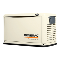
Do you have a question about the Generac Power Systems Guardian 5410 and is the answer not in the manual?
Flowchart for diagnosing voltage and frequency issues.
Flowchart for troubleshooting zero or low residual AC voltage output.
Flowchart for diagnosing voltage/frequency droop under load.
Flowchart for troubleshooting engine overspeed warnings.
Flowchart for diagnosing priming issues on gasoline models.
Flowchart for troubleshooting when the engine fails to crank.
Flowchart for diagnosing engine crank-but-no-start issues in gasoline units.
Flowchart for diagnosing engine crank-but-no-start issues in LP units.
Flowchart for troubleshooting hard starting and rough running in gasoline units.
Flowchart for troubleshooting hard starting and rough running in LP units.
Flowchart for diagnosing high oil temp or low oil pressure faults.
Flowchart for troubleshooting a blown 7.5A fuse.
Procedures to check generator output voltage and frequency at no load.
Checks the stepper motor's movement for proper throttle control.
Tests the excitation circuit by applying battery voltage to the rotor.
Checks if field boost current is delivered to the rotor during cranking.
Tests the stator excitation winding for open circuits.
Checks sensing leads and power windings for proper resistance and shorts.
Verifies continuity of wires connecting the voltage regulator to the brush terminals.
Inspects brushes and slip rings for wear, damage, or oxide film.
Tests the rotor assembly for open or shorted conditions.
Checks if the main circuit breaker is closed and has continuity.
Checks generator output voltage and frequency under load.
Determines if the generator's rated capacity is exceeded by the applied loads.
Tests if the engine cranks and the priming function works.
Verifies fuel pump operation and fuel flow to the carburetor.
Checks if the 7.5 amp fuse has blown, preventing cranking.
Assesses battery condition and cable connections for proper voltage.
Verifies battery voltage is supplied to the PCB for cranking.
Checks continuity of the wire that initiates cranking when grounded.
Tests for ignition spark using a spark tester.
Checks and adjusts the air gap for ignition magnetos.
Checks engine sealing and compression using leak down and compression tests.
Presents the generator's electrical schematic and wiring diagram.
| Start Type | Electric |
|---|---|
| Voltage | 120/240 V |
| Frequency | 60 Hz |
| Fuel Type | Gasoline/Propane |
| Warranty | 3 years |

