Section 7
DIAGNOSTIC TESTS
3. If “Infinity” was not measured in Step 15, repair
or replace grounded Wire 18A between the J1
Connector and the insulated terminal stud or
defective insulated terminal stud.
4. If sparking still does not occur after adjusting the
armature air gap, testing the ground wires and
performing the basic flywheel test, replace the
ignition magneto(s).
Note: Before replacing the Ignition Magneto, check
the Flywheel Magnet.
CHECKING FLYWHEEL MAGNET:
The flywheel magnet rarely loses its magnetism. If you
suspect a magnet might be defective, a rough test can
be performed as follows:
1. Place the flywheel on a wooden surface.
2. Hold a screwdriver at the extreme end of its han-
dle and with its point down.
3. Move the tip of the screwdriver to about 3/4 inch
(19mm) from the magnet. The screwdriver blade
should be pulled in against the magnet.
FLYWHEEL KEY:
In all cases, the flywheel taper is locked on the crank-
shaft taper by the torque of the flywheel nut. A keyway
is provided for alignment only and theoretically carries
no load.
If the flywheel key becomes sheared or even partially
sheared, ignition timing can change. Incorrect timing
can result in hard starting or failure to start.
Remove and inspect flywheel key for damage.
TEST 32 – CHECK VALVE ADJUSTMENT
DISCUSSION:
The valve lash must be adjusted correctly in order to pro-
vide the proper air/fuel mixture to the combustion chamber.
ADJUSTING VALVE CLEARANCE:
Adjust valve clearance with the engine at room tem-
perature. The piston should be at top dead center
(TDC) of its compression stroke (both valves closed).
An alternative method is to turn the engine over and
position the intake valve fully open (intake valve spring
compressed) and adjust the exhaust valve clearance.
Turn the engine over and position the exhaust valve
fully open (exhaust valve spring compressed) and
adjust the intake valve clearance.
Correct valve clearance is given below, in INCHES
(MILLIMETERS).
Intake Valve 0.002-0.004 (0.05-0.1)
Exhaust Valve 0.002-0.004 (0.05-0.1)
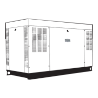
1. Loosen the rocker arm jam nut. Use a 10mm allen
wrench to turn the pivot ball stud while checking the
clearance between the rocker arm and valve stem
with a feeler gauge (see Figure 7-39).
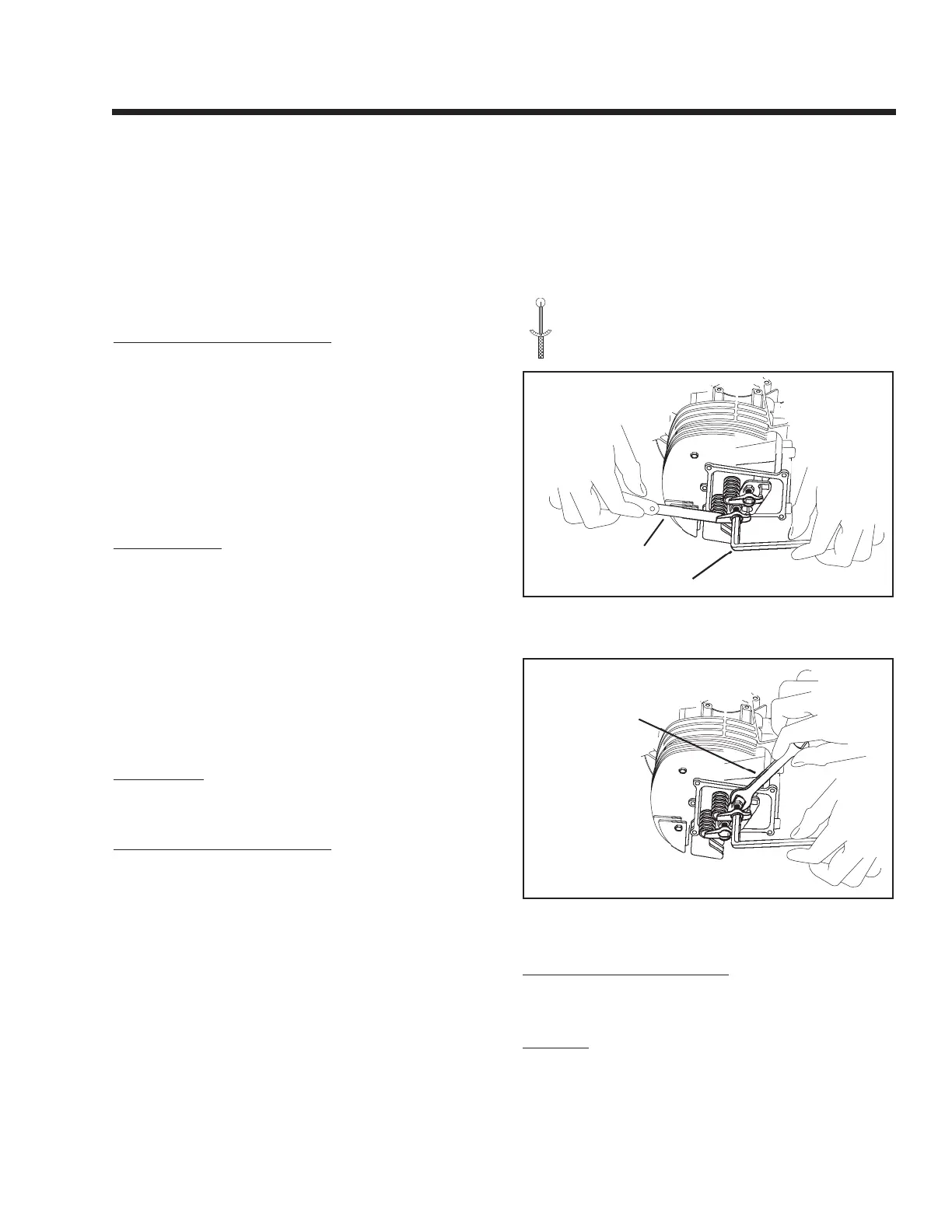
2. When clearance is correct, hold the pivot ball stud
with the allen wrench and tighten the rocker arm
jam nut to the specified torque with a crow’s foot.
After tightening the jam nut, recheck valve clear-
ance to make sure it did not change.
TORQUE SPECIFICATION
ROCKER ARM JAM NUT
174 inch-pounds
Figure 7-39 – Adjusting Valve Clearance
Figure 7-40 – Tightening the Jam Nut
INSTALL ROCKER ARM COVER
1. Use a new rocker arm cover gasket. Install the
rocker arm cover and retain with four screws.
RESULTS:
Adjust valves to specification and retest. If problem
continues, go to Test 35.
Page 57

 Loading...