Section 7
DIAGNOSTIC TESTS
6
0
4
13
13
2
4
22S
11S
15
105 VAC
JUMPER WIRE
WIRES 4 REMOVED FROM
VOLTAGE REGULATOR
VOLTAGE
REGULATOR
FUSE HOLDER (F1)
RED TEST LEAD
BLACK TEST LEAD
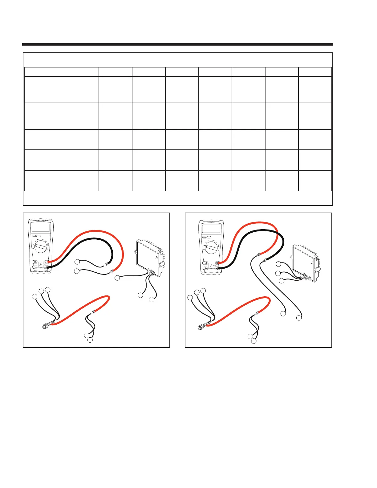
Figure 7-4. – Fixed Excitation Test, Step B
4. Disconnect Wire 2 from the Voltage Regulator
(VR) and connect one meter test lead to that wire.
Disconnect Wire 6 from the Voltage Regulator and
connect the other meter test lead to that wire. See
Figure 7-4. Start the generator and measure the
AC voltage. It should be above 60 volts. Record
the results and stop the generator.
5. Re-connect Wire 2 and Wire 6 to the Voltage
Regulator.
6
0
4
13
13
2
4
22S
11S
15
JUMPER WIRE
WIRES 4 REMOVED FROM
VOLTAGE REGULATOR
VOLTAGE
REGULATOR
FUSE HOLDER (F1)
RED TEST LEAD
BLACK TEST LEAD
95 VAC
Figure 7-5. – Fixed Excitation Test, Step C
6. Disconnect Wire 11S from the Voltage Regulator
(VR) and connect one meter test lead to that wire.
Disconnect Wire 22S from the Voltage Regulator
and connect the other meter test lead to that wire.
See Figure 7-5. Start the generator and mea-
sure the AC voltage. It should be above 60 volts.
Record the results and stop the generator.
Page 38
TEST 4 RESULTS
A B C D E F G
VOLTAGE RESULTS
WIRE 2 & 6
EXCITATION WINDING
ABOVE
60 VAC
ABOVE
60 VAC
BELOW
60 VAC
ZERO OR
RESIDUAL
VOLTAGE
(5-12 VAC)
BELOW BELOW
60 VAC
ABOVE
60 VAC
VOLTAGE RESULTS
WIRE 11S & 22S
POWER WINDING
SENSE LEADS
ABOVE
60 VAC
BELOW
60 VAC
ABOVE
60 VAC
ZERO OR
RESIDUAL
VOLTAGE
(5-12 VAC)
BELOW BELOW
60 VAC
ABOVE
60 VAC
ROTOR AMP DRAW
RV45
(MODEL 5410/5411)
1.1 A
± 20%
1.1 A
± 20%
1.1 A
± 20%
ZERO
CURRENT
DRAW
1.4 A .85 A
± 20%
ZERO
CURRENT
DRAW
ROTOR AMP DRAW
RV55
(MODEL 5412/5413)
.85 A
± 20%
.85 A
± 20%
.85 A
± 20%
ZERO
CURRENT
DRAW
1.2 A .85 A
± 20%
ZERO
CURRENT
DRAW
ROTOR AMP DRAW
RV65
(MODEL 5414/5415)
1.2 A
± 20%
1.2 A
± 20%
1.2 A
± 20%
ZERO
CURRENT
DRAW
1.5 A 1.2 A
± 20%
ZERO
CURRENT
DRAW
(MATCH RESULTS WITH LETTER AND REFER TO FLOW CHART – Problem 2 on Pages 28 & 29)
 Loading...