Section 7
DIAGNOSTIC TESTS
in its coil, tighten the two screws. Verify that the
choke solenoid plunger and linkage move freely
without any drag or resistance that may restrict
movement.
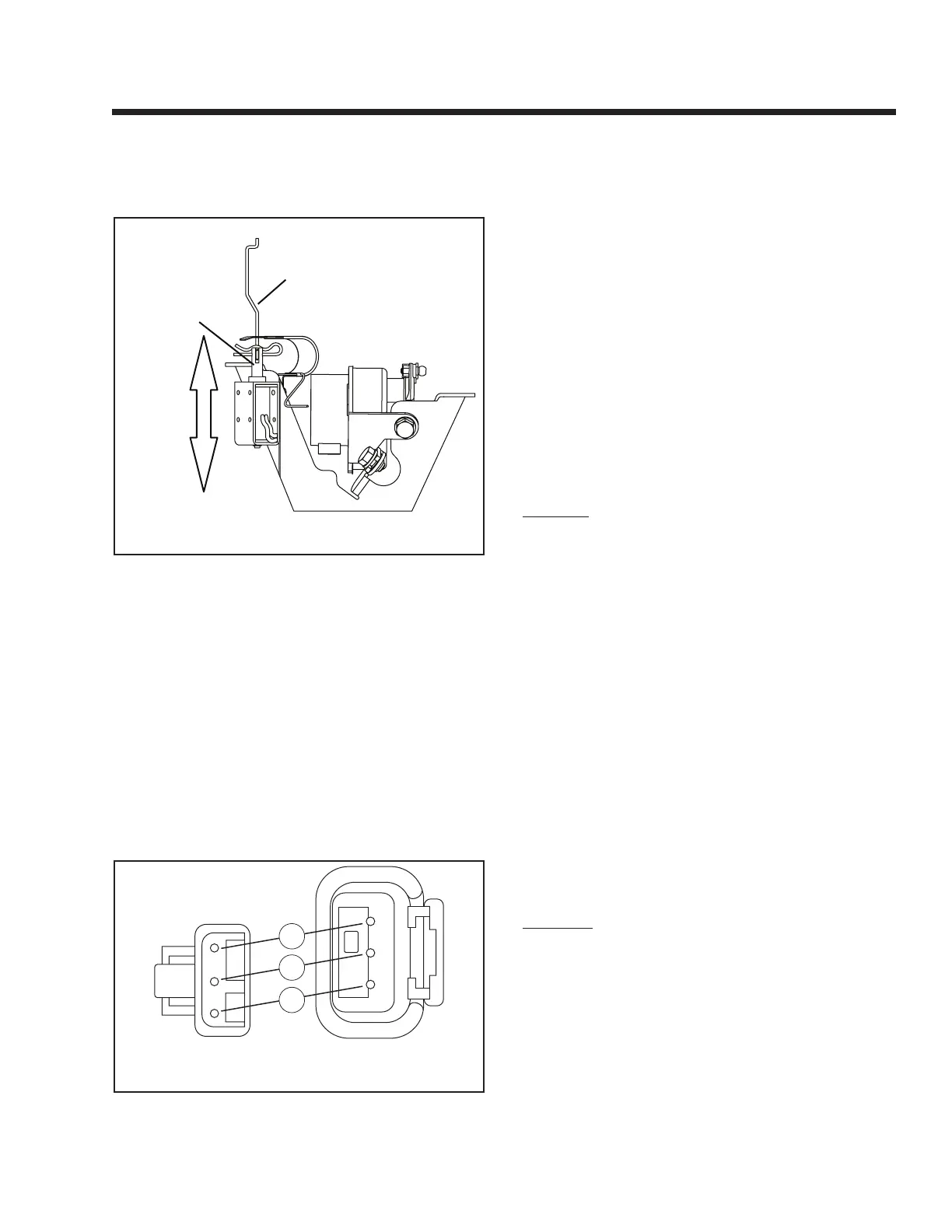
CHOKE CONTROL ROD
CHOKE SOLENOID
MOVES VERTICALLY
PLUNGER
Figure 7-42. – Choke Solenoid Adjustment
4. Disconnect Connector 3: Set the VOM to measure
DC voltage. Connect the positive (+) test lead to
Wire 90 (Pin 2) of Connector 3 going to the control
panel. Connect the negative (-) test lead to frame
ground. Activate the Start-Stop Switch to “START.”
During cranking, battery voltage should be mea-
sured cyclically every two seconds.
5. If battery voltage was not measured in Step 4,
check at J1 Connector: Connect positive (+) test
lead to Pin Location J1-2 at the Printed Circuit
Board. Connect the negative (-) test lead to frame
ground. Activate the Start-Stop Switch to “START.”
During cranking, battery voltage should be mea-
sured cyclically every two seconds.
1
3
90
2
2
3
1
14
14
TO CONTROL
PANEL
TO CHOKE
SOLENOID
Figure 7-43. – Connector 3
6. Set the VOM to measure resistance.
Disconnect
Connector 3 from the Choke Solenoid.
Connect
one test lead to Wire 0 (Pin 1) of Connector 3,
going to the control panel. Connect the other test
lead to frame ground.
“
Continuity” should be mea-
sured.
7. Set the VOM to measure resistance. Disconnect
Connector 3. Connect one meter test lead to
Wire 90 (Connector 3, Pin 2) going to the Choke
Solenoid. Connect the other meter test lead to
Wire 0 (Connector 3, Pin 1). Approximately 3.7
ohms should be measured. (Current draw of
Choke Solenoid at nominal voltage is 3.4 amps).
Short to Ground:
8. Set the VOM to measure resistance. Disconnect
Connector 3. Connect one meter test lead to Wire
90 (Connector 3, Pin 2). Connect the other meter
test lead to the metal Choke Solenoid housing.
“Infinity” should be measured. If “Continuity” is
measured, a short to ground exists.
RESULTS:
1. If Choke operation is good, go to Test 32 for
Problem 7, “Engine Cranks but Won’t Start”
(Section 6). Go to Test 41 for Problem 8, “Engine
Starts Hard and Runs Rough”.
2. If battery voltage was measured in Step 5 but
not measured in Step 4, repair or replace Wire
90 between Printed Circuit Board (PCB) and
Connector 3.
3. If battery voltage is not measured in Step 5 during
engine cranking, replace PCB.
4. If
“
Continuity” is not measured in Step 6, repair or
replace Wire 0 between the ground terminal and
Connector 3.
5. If Choke Solenoid coil resistance is not mea-
sured or is incorrect in Step 7, replace the Choke
Solenoid.
TEST 35 – CHECK ENGINE / CYLINDER LEAK
DOWN TEST / COMPRESSION TEST
GENERAL:
Most engine problems may be classified as one or a
combination of the following:
❏Will not start.
❏ Starts hard.
❏ Lack of power.
❏ Runs rough.
❏ Vibration.
❏ Overheating.
❏ High oil consumption.
Page 59

 Loading...