Section 2
MAJOR GENERATOR COMPONENTS
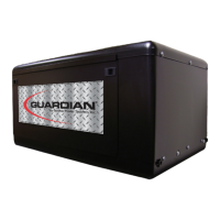
Leads 2 & 6 = Stator Excitation Winding
Leads 11S & 22S = Voltage Sensing Leads
Leads 11 & 22, 33 & 44 = AC Power Windings
Stator
2
6
11
22
33
44
11S
22S
Figure 2-2. – Stator Output Leads
BRUSH HOLDER
The brush holder is retained in the rear bearing car-
rier by two M5 screws. It retains two brushes, which
contact the Rotor slip rings and allow current flow
from stationary parts to the revolving Rotor. The posi-
tive (+) brush is located nearest the Rotor bearing.
Figure 2-3. – Brush Holder
EXCITATION CIRCUIT COMPONENTS
GENERAL:
During operation, the Rotor’s magnetic field induces
a voltage and current flow into the Stator excitation
winding. This results in AC output delivered to a volt-
age regulator via Wires 2 and 6.
REGULATOR
VOLTAGE
2
2
0
6
22S
4
11S
22S
11S
6
0
4
22S
11S
BA
DPE WINDING
6240
FIELD
0
+
-
Figure 2-5. – Schematic: Excitation Circuit
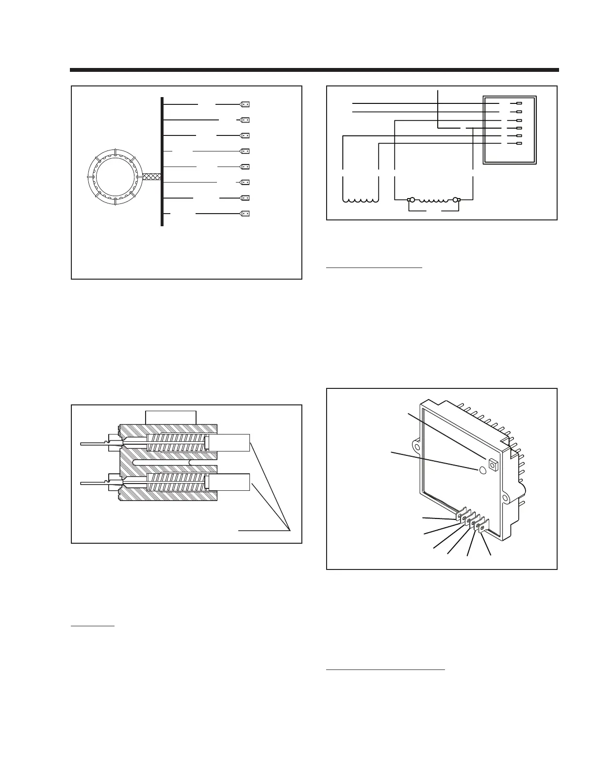
VOLTAGE REGULATOR:
Six (6) leads are connected to the voltage regulator
as follows:
• Two(2)SENSINGleadsdeliverACTUALACoutput
voltage signals to the regulator. These are Wires
11S and 22S.
• Two(2)leads(Wires4and0)delivertheregulated
direct current to the Rotor, via brushes and slip
rings.
• Two(2)leads(Wires6and2)deliverStatorexcita-
tion winding AC output to the regulator.
VOLTAGE
ADJUST POT
LED
6
0
2
4
22S
11S
Figure 2-7. – Voltage Regulator
The regulator mounts a “VOLTAGE ADJUST”
potentiometer, used for adjustment of the pre-set
REFERENCE voltage. A lamp (LED) will turn on to
indicate that SENSING voltage is available to the
regulator and that the regulator is turned on.
ADJUSTMENT PROCEDURE:
With the frequency set at 60 Hertz and no load on the
generator, slowly turn the voltage adjust pot on the volt-
age regulator until 122-126 VAC is measured. If voltage is
not adjustable, proceed to Section 6 – Troubleshooting.
Page 9
 Loading...