Do you have a question about the Generac Power Systems 04389-3, 04456-3, 04390-3 and is the answer not in the manual?
| Brand | Generac Power Systems |
|---|---|
| Model | 04389-3, 04456-3, 04390-3 |
| Category | Inverter |
| Language | English |
Emphasizes the importance of reading the entire manual.
Outlines general safety precautions for installation and operation.
Instructions for inspecting contents upon delivery for damage.
Describes engine protection systems against damaging conditions.
Explains the National Electrical Code requirement for AFCI breakers.
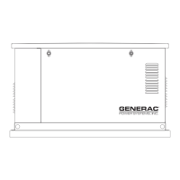
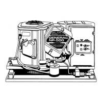
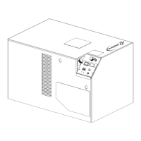
Identifies key components of the generator via diagrams.
Provides detailed technical specifications for generator and engine models.
Lists electrical specifications for different generator models.
Lists engine specifications for different generator models.
Explains the conditions under which the "System Set" LED is illuminated.
Details fuel types, pressures, and recommendations for operation.
Provides fuel consumption rates for different loads and fuel types.
Step-by-step instructions for switching between natural gas and propane.
Specific reconfiguration steps for the 7kW engine.
Specific reconfiguration steps for 12kW and 15kW engines.
Guidelines for selecting an optimal and safe installation location.
Rules for indoor installation of the transfer switch enclosure.
Specific installation rules for the transfer switch.
Step-by-step procedure for installing the generator battery.
Safety warnings and precautions for handling the battery.
Pre-start checks and procedures before initial generator operation.
Procedure to verify the proper functioning of the transfer switch.
Performing essential electrical checks before generator operation.
Steps for testing the generator with electrical loads applied.
Verifying the generator's ability to operate automatically.
Procedure to adjust the fuel regulator for optimal performance.
Adjusting the engine governor for correct frequency and voltage.
Specific governor adjustment steps for 7kW units.
Specific governor adjustment steps for 12kW and 15kW units.
Adjusting the voltage regulator for correct output voltage.
Recommended steps for the initial generator break-in period.
Explains the function and use of the main operating switch.
Details how to set the switch for automatic system operation.
Describes how to shut down the engine and prevent automatic operation.
Explains how to start the engine manually.
Steps to select and initiate automatic operation.
Information on the 12VDC accessory outlet and its limitations.
Details the 120VAC GFCI outlet for external power.
Outlines the step-by-step process of automatic generator startup and shutdown.
Procedures for manually transferring power between utility and standby sources.
Steps to start the generator and activate the transfer switch manually.
Steps to transfer power back to utility and shut down the generator.
How to set the timer for automatic weekly generator exercise.
Describes built-in safety features that protect the generator.
Explains the function of the low oil pressure shutdown switch.
Details the high temperature shutdown switch and its reset.
Describes the overcrank protection feature and its reset procedure.
Explains the overspeed protection that prevents engine damage.
Identifies and explains the purpose of the generator's fuses.
Procedure to check the engine oil level using the dipstick.
Step-by-step guide for performing an engine oil change.
Specifies recommended oil types and viscosity for the engine.
Detailed steps for draining and refilling engine oil.
Procedure for replacing the engine oil filter.
Instructions for cleaning or replacing the engine air cleaner.
Guidance on inspecting, cleaning, gapping, or replacing spark plugs.
Procedures for inspecting and maintaining the generator's battery.
Instructions for adjusting valve clearance on specific engine models.
Importance of clear air inlets and outlets for proper cooling.
Precautions and actions required if the generator is submerged in water.
Recommendations for protecting the enclosure and linkages from corrosion.
Steps for preparing the generator for extended storage.
Detailed procedure for taking the generator out of service.
Procedures for returning the generator to service after storage.
Provides a schedule for routine inspection, change, and cleaning tasks.
A guide to common problems, their causes, and suggested corrections.
Diagram illustrating the wiring connections for the engine.
Explains the symbols and abbreviations used in the wiring diagrams.
Diagram showing the electrical components within the control panel box.
Indicates a specific location relative to the bearing.
Diagram of the electronic voltage regulator and its connections.
Diagram of the control printed circuit board and its connectors.
Shows how the generator connects to the customer's electrical system.
Diagram illustrating the wiring connections for the engine.
Explains the symbols and abbreviations used in the wiring diagrams.
Diagram showing the electrical components within the control panel box.
Shows how the generator connects to the customer's electrical system.
Diagram illustrating the wiring connections for the engine.
Explains the symbols and abbreviations used in the wiring diagrams.
Diagram showing the electrical components within the control panel box.
Shows how the generator connects to the customer's electrical system.
Diagram illustrating the wiring connections for the engine.
Explains the symbols and abbreviations used in the wiring diagrams.
Diagram showing the electrical components within the control panel box.
Shows how the generator connects to the customer's electrical system.
Shows the wiring for an 8-circuit load center.
Shows the wiring for an 8-circuit load center.
Explains abbreviations used in the load center wiring diagram.
Shows the wiring for a 12-circuit load center.
Shows the wiring for a 12-circuit load center.
Explains abbreviations used in the load center wiring diagram.
Exploded view of the generator enclosure with numbered parts.
Exploded view of the control panel with numbered parts.
Exploded view of the 7kW load center assembly.
Exploded view of the 12/15kW load center assembly.
Exploded view of the GT-990/760 engine (part 1).
Exploded view of the GT-990/760 engine (part 2).
Exploded view of the 7kW generator assembly.
Exploded view of the 12/15kW generator assembly.
Exploded view of the GN410 engine (part 1).
Exploded view of the GN410 engine (part 2).
Diagrams showing overall dimensions and installation clearances.
Details warranty rights and obligations for California emissions.
Outlines responsibilities of manufacturer and owner regarding warranty.
Specifies coverage details for emission control system components.
Lists owner's responsibilities for maintaining warranty coverage.
Lists specific parts covered under the emission control system warranty.
Outlines warranty coverage periods for different generator components.
Lists exclusions from the warranty coverage.