General Information
6 Owner’s Manual for 60 Hz Air-Cooled Generators
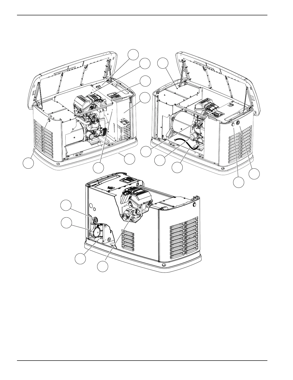
Figure 2-2. 11kW–22kW—Components and Control Locations
A. Lock with Cover E. Battery Compartment
(Battery not supplied)
J. Oil Fill Cap N. Sediment Trap
B. Main Line Circuit
Breaker (Generator
Disconnect)
F. Exhaust Enclosure K. Oil Filter O. Fuel Regulator
C. Airbox with Air Cleaner G. Status LED Indicators L. Composite Base P. Fuel Inlet
D. Control Panel H. Oil Drain M. Oil Dipstick Q. Data Plate Location

 Loading...


