4 Natural gas fuel system requirements
__ 5 [P gas fuel system requtreq_nts
_ 6 EleClncnlconnect_ons
7 Automati_ co_ntrolsystem conne,:bons
__ 8 Prep,_'atlon Before InRi31Starfup
9 Batten/ Inslaltebon
10 Initial Stirrup and Testing
Generator and Transfer Switch Location
Ge_retor Location In, tail _e generator ouldoors and m
an aria where adequate coo_ng mr and yent_atmg a_l /_11
be evaiteb_ Remember exhaust gases contain deadly
carbon_xlde gas and WOf_r ventllatwn is requwed to
dissipateexheustoutp_ Theenglne generatorrequTre$ an
adequate, unobstructed flow ofCoo_ngmr for p(oper opera
tton
OANGER _ EXHAUST GASES CONTAIN DEADLY
CARBON MONOXIDE GAS. 1HIS DANGEROUS GAS,
IF BREATHED IN SUFFICIENT CONCENTRATIONS,
CAN CAUSE UNCONSCIOUSNESS OR EVEN DEATH
OPERATE THE GEhlERATOR ONLY IN OPEN, WELL
YENTILATED AREAS. WHERE EXHAUST GASES
WILL NOT ACCUMULATE AND ENDANGER PEOPLE
_'HERE MUST BE NO POSSIBILITY OF EXHAUS1
;ASES ENTERING A BUILDING OCCUPIED BY
)EOPLE OR ANIMALS
Install_ generatorwhereg(ass, leaves snow, arc. wel
r_4 accumutatleand obstruofcoofJogair openingsm its
_t #prevNlng vv_xtzare Nk_ytocausel_ock
ageoflhe coo_ av openings,youmay wishto¢OnSKN_
theuseol a wtndlyeJ to p'oteclme generator
The Install_ mu_t also consider wate_ levels at the resist-
laiton site Never Install the generator on low ground, where
*atm m6gl_dse and tndanger _DeufCt
Fk_Mly,Insleit Ihl geNcator lul €oes U Ix:411bteIo the fuel
suPl_ TI_ wM reduce Ihe cost of pq_tg nine
Alow _l,Nlua_ room|m_uncl=it tide. offf_, ge_eratmtof
m_nWWnm, mm_i _ml r_ Agenarat n_e mm slow
mleml 3 hN_of c_mmn_eon Jl m o_t_ un_
Trm SwNch LOCMIon" toMait the _lntfet switch m-
_oore..,= close u pm.dil_le _ I_} LrTILrrY ix, we_ seun:e
_l_tc_ ser_ce e_,rmlce This wl reduce me coat of
Oenerator Mounting and Support
(]llm_fato4' moqJnlk_ dthleflato_ ire ehotwl on Pl_e 4 The
Wm_ocs comp.rlmem encmum sh_ld be seox_
mounled los _.m_¢ sMi_, uslnp 1/4 th0h mNon,y typ_
_ b_ _ wmd_ I_1_ to__ _ The
Gramme mb should Ix_ M Me_ 3 Inohe_ mk:k and sheuM
oxle_l IN;y(nd the €omperlmen¢ at lesmt 3 inches on aN
€des 8eeFIgum2 BetwetolevatmesMb, sothatme
gont_tor l0rooa_ ona tovoteurtaeo
F OutP • Mount the Generator to a Cement S/,JI3
iS 43
38 13 _ leg _:m)
196 8cm) i
F
/,
/
/
I // CEMENT SLAB
-y
Transfer Switch Mounting
See Page 4 for Transtor Sw_tch mounting d_m_ns+ons
Moun_the sw_tch to a strong,, _ suppm'flng struchJre that
can adequately support its wetghl it necessary _vel Ih,_
sw,tc_ Is prevent d|stod,o_ Th0scan be done by plaanq
washers befween fhe swtlch and supporting struOure
when levekng m necessary
AUTION_ Never Inl_ill the trlineter swllch where]
e|efl corrosive quids, or lny liquid might drip onto_
en¢lolure Prots_t Iho Switch egllnel dust dlrt I
Olslure, construcUon grit, end corrosive vef.ols mi
I limit J
Natural and LP GBS Fuel System Installation
Whenplan_mg the fuel supply system instal_lofl keep
fuel ppmgrunsas sh_1 espossibleforcostreduc_m
DANGER! GASEOUS FUELS ARE HIGHLY EX,
PLOSIVE THE SLIGHTEST SPARK WILL RESULT ll_
FIRE OR AN EXPLOSION ALL APPLICABLE FUEL,
GAS CODES, STANOAROS ANO REGULATIONS
MUST BE STRICTLY COMPLIED WITH FOR SAFETY
INSTALLATION OF GASEOUS FUEL PIPING AN r
COMPONENTS SHOULD BE ACCOMPLISHED BY _1
COMPETENT. OUALIFIEO GASEOUS FUEL TECH
_ICIAN.
NOTE The lollow_ e_omtlton I_ providedto islsl
_s fu_ ted_nk:_n _npl_nnlngt_e InatilMlon o_the
fue4supplysysNm_ In no way mustt_e In_om_ton be _
t_ix_d to con_lclw_ idol, stateor nat_ guol.gas
Cocalul_wqhyourgel |lUp orIo_it Ikwmarshal
_ anyquestionsshouldwIM
ThegllJ fuelsyatemIsIhown mFigure3 A I_ ofIt_dble
fuel Ins. approv_l for uN w_h ges4mushJats,shoui_ ,
mteitedl_m_e_tt_g_e_lor_nd_l_lfu_l_V_g 1 s
nexi_ I_e shoed _ s,.,_le_ey lo_i to prsve_ I_e._0e
it e_e genoroto_ sheuld sNfl o_satlle
Rind gASeOUSfuotp_p_ng0houndbe m bteck_on, i_'otD_'ty
InstekKI lind eup_ O0 NOT USIE GALVANIZED
PIPING. THE GALVANIZED COATING WILL FLAKE _f: F
AND CLOG REGULATORS AND LINES
Gaseous fuel pcessure at the m_eIto lbe r_J_ator must be
_ mc_es of wate¢ (6 38 ounces per inch') Under no ck
cum$1ances sh_Jid rear.or inl_ pre,_sureb_ more than
26 Inches of water ( 15 ounces p_' Inch') To meas_o sys.
tern pressure use • water' mw_x_._lw' or in accurMe
gauge cMlxated in ou_c_s pie square inch
The syatern was property arousal III It_ hlclory, u_ng
nalu_at gas If LP Sm (ptof_lne) _ Io b_ U_KI es e fuW,
rea_ustme_1 of 1he system will be necessary See AD
JUSTMENTS seclton
F,gure 3 The Generator Fuel System
WARNING.t: BE SAFE• INSTALL THE GASEOUS FUEL
SYSTEM PER APPLICABLE STANDARDS AND
_OOES. GASEOUS FUEL LINES MUST BE PROPER-
LY PURGED AND LEAK TESTED SEFORE PLACING
THE GENERATOR INTO SERVICE. NO LEAKAGE IS
PERMITTED. NATURAL GAS IS LIGHTER THAN AIR
&NO TENDS TO SETrLE IN HIGH AREAS• LP GAS
[PROPANE) IS HEAVIER THAN AIR AND SETTLES IN
LOW AREAS. EVEN THE SLIGHTEST SPARK CAN IG-
MITE THESE GASES AND CAUSE FIRE OR AN EX-
PLOSION
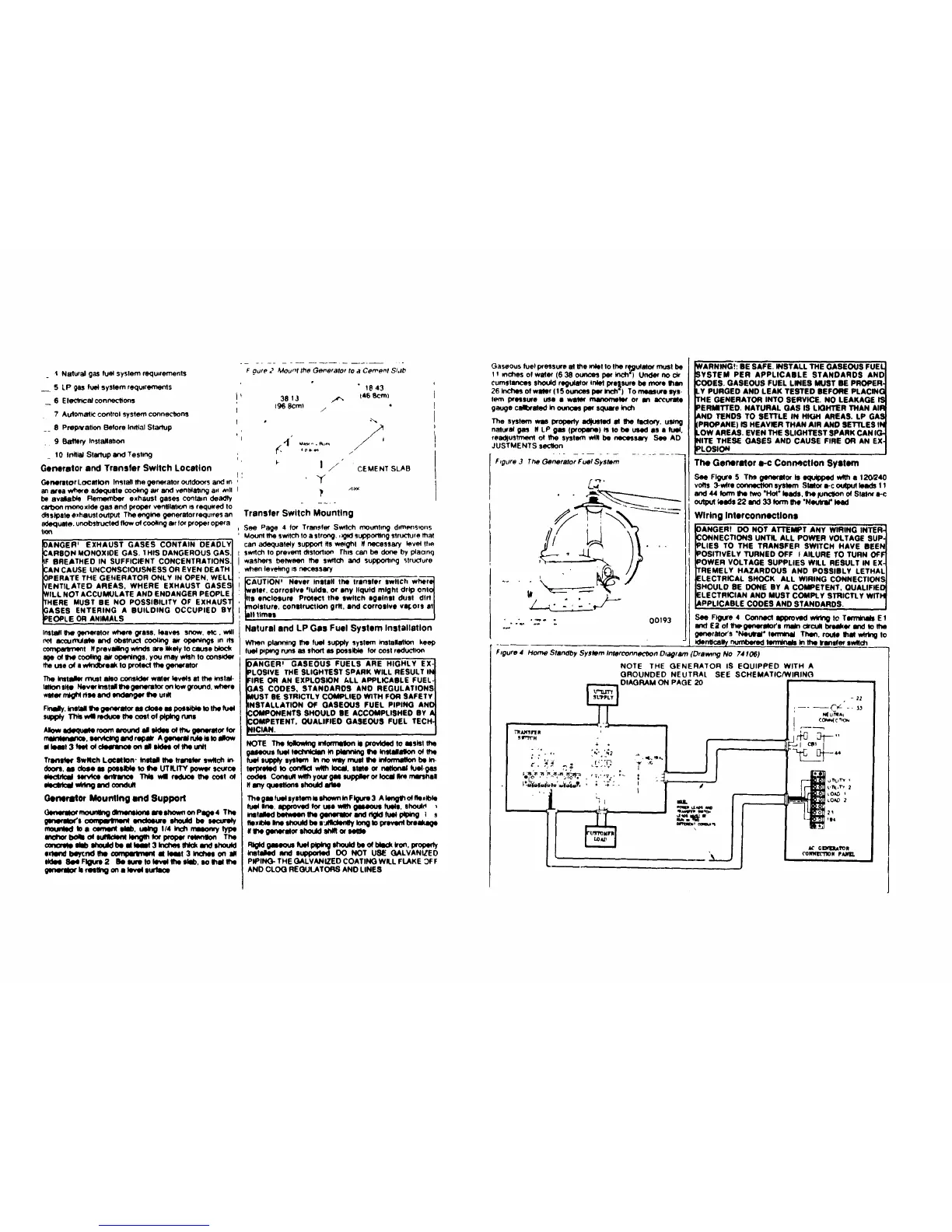
The Generator _-c Connection System
See FigureS The geneqll_' is equipped_ • 120/240
volls 3-w_re_ system Slalor _-c ou(pulleads11
and44 fo_mI1_ fwo "Hof"leeds,lie fun_itonof Stalnr_-c
outpul_e-de22 w_d33 Iormt_e "N_utrat"teed
Wiring Interconnectlons
00193
DANGER! DO NOT A1"rEMPT ANY WIRING INTER-
DONNECTIORS UNTIL ALL POWER VOLTAGE SUP.
PLIES TO THE TRANSFER SWITCH HAVE BEEN
POSITIVELY TURNED OFF f ALLURE TO TURN OFF
POWER VOLTAGE SUPPLIES WILL RESULT IN EX-
TREMELY HAZARDOUS AND POSSIBLY LETHAL
ELECTRICAL SHOCK ALL WIRING CONNECTIONS
SHOULD BE DONE BY A COMPETENT, QUALIFIED
ELECTRICIAN AND MUST COMPLY STRICTLY WITH
APPLICABLE COOES AND STANDARDS.
See Figure 4 Connect Ippto_KI wM_g IO Tm E 1
and E;I of I_generatofs main circuit brNke_ and to the
garlerg4or's "NeUral" ten_ Tl't_l, route that wtt_g to
td_ntl_m_ numbered temVnats in tt_ trlnt_,_' synch
F_gure 4 Home Standby Systom Interconne_Oon O_agtarn (Drawnng No 74 f06)
NOTE THE GENERATOR IS EQUIPPED WITH A
GROUNDED NEUTRAL SEE SCHEMATIC/WIRING
i /
TI_ANSr[ R
• , h' N2
_'t,_ ,_y_-"_:_, , , _,-,;-,,
eq , • • •
'l
~ 12
_UntA*
_0_ _
 Loading...