4 Owner’s Manual for Portable Generator
Section 2 General Information and Setup
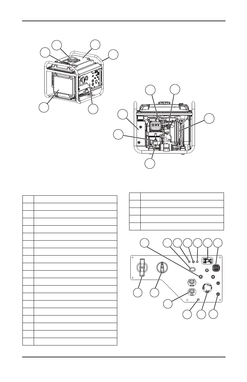
Figure 2-1. Features and Controls
TABLE 1. Generator Components
Figure 2-2. Control Panel
20
13
12
25
22
21
23
19
14
15
16
005456
24
006092
1Low Oil Warning
2 Overload Warning
3 AC Power Light
4 Hour Meter
5 1A/2.1A, 5 VDC USB Outlet
6 AC Breaker
7 120V, 30A Receptacle (NEMA L5-30R)
8 Grounding Location
9 120V, 20A Receptacle
10 Parallel Outlets
11 Engine Smart Control (ESC)
12 Frame
13 Fuel Gauge
14 Fuel Tank Cap
15 Fuel Tank
16 Control Panel
17 Off/On/Choke Switch
18 Recoil Starter
19 Inverter Module
20 Muffler
21 Oil Drain
22 Oil Fill
23 Air Cleaner
24 Carburetor
25 Spark Plug
11 1 2
8
5
18
6 3
7
10
9
4
17
006093