Owner’s Manual for Generator 9
General Information
Controller Features and Functions
Home Button
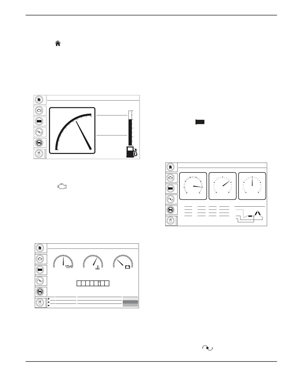
The Home ( ) button is the default screen of the
controller and will display after the controller is powered
up and the unit management software is loaded. It
displays a live readout of the kW meter, percent of load
used (gauge), selected phase, volts and amps being
produced by the generator, and the fuel level with time
until empty. The controller will automatically return to this
screen from any other screen after a period of inactivity.
Figure 2-5. Home Button Screen
Engine Button
The Engine ( ) button displays the oil pressure,
coolant temperature and battery voltage on three main
gauges. Below the gauges is an hour gauge displaying
the total run time on the engine. At the bottom of the
screen, this screen also displays maintenance alarm
status with the time remaining (black text), or the time
past (red text) a scheduled maintenance task, along with
the description of the maintenance procedure and the
action that will take place when the timer trips the alarm.
Figure 2-6. Engine Button Screen
NOTE: If the measured value is outside the range of a
gauge, the needle will not be displayed. The digital value
below the gauge will still show the measured value.
• Oil Press: Displays engine oil pressure. Current
coolant temperature is displayed directly below the
gauge at all times. The gauge registers oil pressure
between 0-100 psi (0-689 kPa). Normal operating
pressure is between 35-80 psi (241-552 kPa).
• Coolant Temp: Displays engine coolant
temperature. Current coolant temperature is
displayed directly below the gauge at all times. The
gauge displays coolant temperature between 150°-
250°F (66°-121°C). Normal operating temperature
of the unit is between 180°-200°F (82°-93°C) with
an average ambient air temperature of 70°F
(21°C).
• Battery: Displays the engine battery voltage.
Current battery voltage is displayed directly below
the gauge at all times. The gauge displays battery
voltage between 0-50V. A normal reading is 12-
14V on 12 volt systems and 24-26V on 24 volt
systems (with the engine running).
Generator Button
The Generator ( ) button displays the average
voltage frequency, volts and amps from the generator, as
well as line-to-line voltage and individual line-to-neutral
voltage, amperage and power (kW). This screen also
displays the generator winding configuration set by the
voltage selector switch in the lower right corner.
Figure 2-7. Generator Button Screen
NOTE: When loading the generator, it is important to
observe the amperage to determine the load balance on
each line of the generator. Minor load unbalances,
usually ten percent or less, will not cause any particular
problems. Every effort should be made to distribute the
load equally between all lines.
• Freq: Displays the output frequency in Hertz (Hz).
Normal operating frequency is 60 Hz.
• Volts: Displays the nominal voltage in Volts (V).
• Amps: Displays the AC output amperage
produced by the generator in Amps (A).
Additional information can be found on the electric power
table at the bottom-left side of the screen. This provides
an overview of all three lines and average voltage and
amperage readouts.
Voltage Adjust Button
The Voltage Adjust ( ) button displays the line-to-
neutral and line-to-line voltage averages. The operator
Manual Mode
3 PHASE
Volts
Amps
480
128
106.9 kW
%
0
10
100
110
20
30
40
50
60
70
80
90
Time to Empty
15 hr
Full
3/4
1/2
1/4
Empty
74
%
GEN
V
+
-
002787
GEN
V
+
-
Maintenance
Alarm Hours Description Action
1 174 To Service Oil Maintenance
2 174 To Service Fuel Maintenance
3 174 To Service Air Maintenance
Oil press. Coolant Temp. Battery
Manual Mode
Hrs
13.8
V
0
10
20 30
40
50150
170
190 210
230
250
°F214PSI50.9
100
0
20
40 60
80
0 0 3 2 5 1 5
Warning
Shutdown
Electrical Trip
002788
Manual Mode
GEN
V
+
-
Parallel Low Zig-Zag
L1 (U)
L2 (W)
N
Volt Volt Amp kW
L1-L2 L1
L2-L3 L2
L3-L1 L3
IE
0
0
0
0
0
0
0
0
50
25
0.0
0.0
0.0
AmpVolt
Freq
0
10
20
30 40
50
60
70 0
88
175
263
350 0
13
25
38
50
002789
 Loading...